28 Section D – Electrical Components
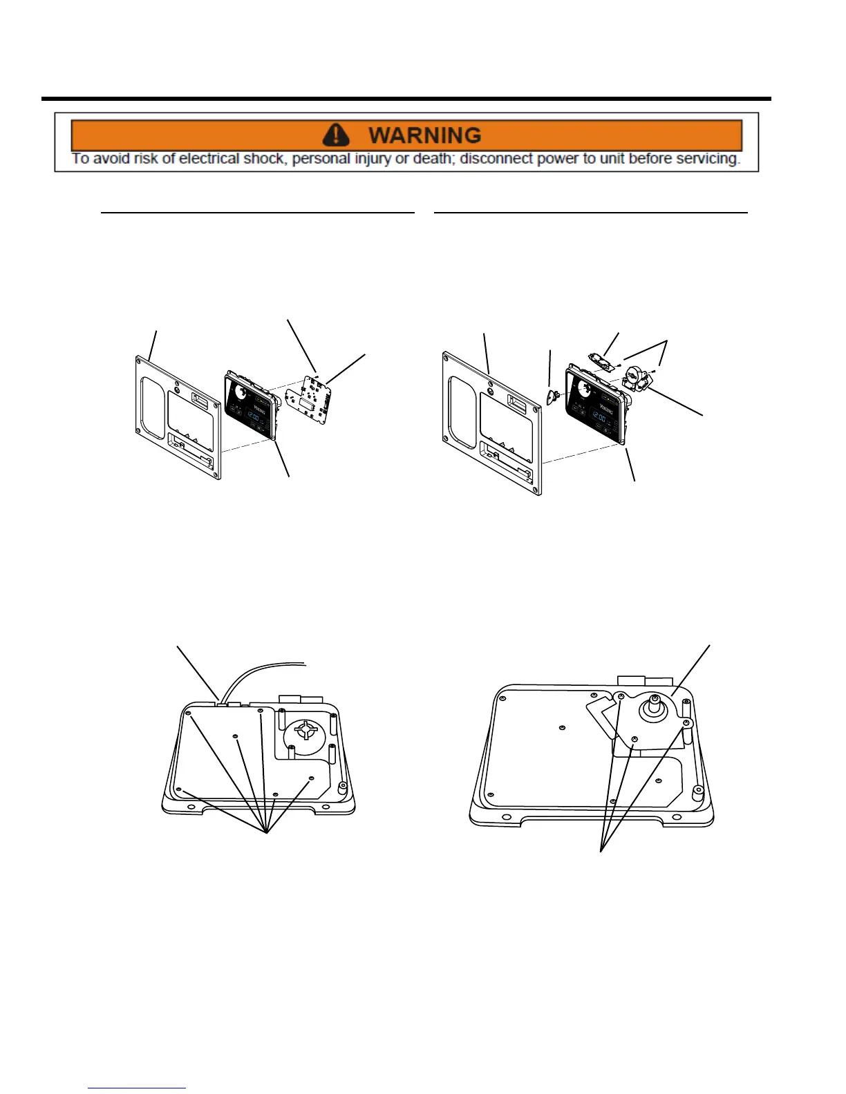
Control Board
REMOVE AND REINSTALL
The control board is used to electronically connect the
compactor’s electronic components.
CONTROL
BOARD
CONTROL
PANEL
SCREWS
DISPLAY
PANEL
1. Remove the control panel assembly (see Control
Panel Assembly, Remove and Re-install). Remove
rear cover from the display module assembly (see
Display Module Assembly, Remove and Re-install).
SCREWS
WIRE
CONNECTOR
2. Remove the wire harnesses from control board (Note
wire locations).
NOTE: In this illustration, the key switch and control
board insulator have been removed for clarity.
3. Remove six Phillips head screws, the printed circuit
board, and the insulator from the display module
frame.
4. Installation is the reverse of removal.
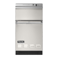
Key Switch
REMOVE AND REPLACE
Part mechanical, part electrical, the key switch gives the
operator three options: ON, OFF and LOCK.
SCREWS
CONTROL
PANEL
INTERLOCK
SWITCH
KEY SWITCH
ASSEMBLY
DISPLAY
MODULE
KEY
1. Remove the control panel assembly (see Control
Panel Assembly, Remove and Re-install) and the
display module. Remove the display module rear
cover and the key.
SCREWS
SWITCH
ASSEMBLY
NOTE: In this illustration, the control board insulator has
been removed for clarity.
2. Remove three Phillips head screws and lift the switch
assembly away from the housing.
3. Noting their locations, transfer the wires to the
replacement switch.
4. Installation is the reverse of removal.