27
Section D – Electrical Components
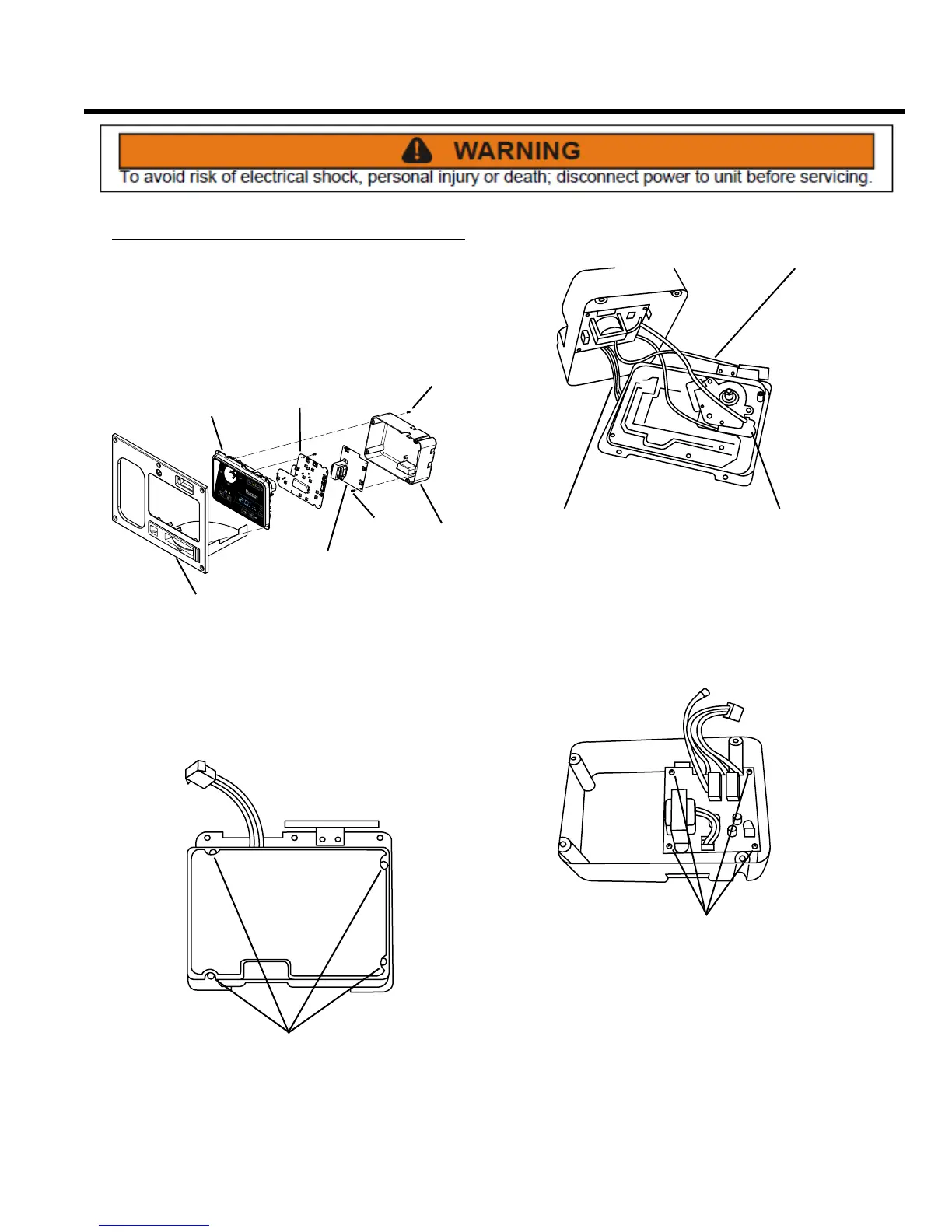
Power Supply Board
REMOVE AND REINSTALL
The power supply board directs electrical power to all
areas of the compactor, including the control board, the
main motor and the odor control motor.
DISPLAY
PANEL
POWER
SUPPLY
BOARD
SCREWS
CONTROL
PANEL
CONTROL
BOARD
SCREWS
REAR
COVER
1. Remove the control panel and display module
assembly (see Control Panel Assembly, Remove and
Re-install and Display Module Assembly, Remove
and Re-install).
SCREWS
2. Remove four Phillips head screws from the display
module assembly rear cover.
CONTROL BOARD
HARNESS
INTERLOCK
SWITCH
WIRE
KEY SWITCH
WIRES
3. Lifting the cover and noting their locations, rmly
but gently disconnect the control board harness, the
wire at the interlock switch, and the key switch wires.
Remove the rear cover. NOTE: Illustration does not
show control board insulator.
SCREWS
4. Remove four Phillips head screws and the power
supply board from the rear cover.
5. Installation is the reverse of removal.