Disassembly
30 ©2010 Viking Preferred Service
To avoid risk of electrical shock, personal injury, or death, disconnect electrical power source to unit, unless test
procedures require power to be connected. Discharge capacitor through a resistor before attempting to service.
Ensure all ground wires are connected before certifying unit as repaired and/or operational.
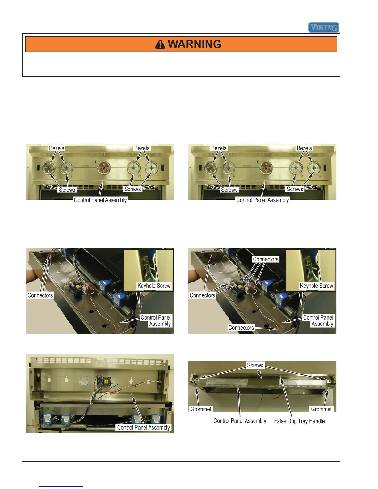
Control Components Accessed
Condition Requirements:
Door Lowered
1. Remove all surface burner and grill knobs.
2. Remove screws and bezels from control panel
assembly where knobs have been removed.
3. Remove two screws from below control panel
assembly.
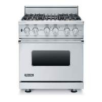
4. Lift up to remove control panel assembly from two
keyhole screws.
5. Tilt control panel assembly forward.
6. Mark and disconnect connectors from the light
switch.
7. Place control panel assembly on protective surface
on the top of range.
8. Reverse procedure for installation.
Control Panel Assembly Removal
Condition Requirements:
Door Lowered
1. Remove all surface burner and grill knobs.
2. Remove screws and bezels from control panel
assembly where knobs have been removed.
3. Remove two screws from below control panel
assembly.
4. Lift up to remove control panel assembly from two
keyhole screws.
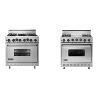
5. Tilt control panel assembly forward.
6. Mark and disconnect all connectors to remove control
panel from range.
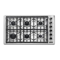
7. Remove grommets from control panel assembly.
8. Remove screws and false drip tray handle from
control panel assembly.
9. Reverse procedure for installation.