Disassembly
38 ©2010 Viking Preferred Service
To avoid risk of electrical shock, personal injury, or death, disconnect electrical power source to unit, unless test
procedures require power to be connected. Discharge capacitor through a resistor before attempting to service.
Ensure all ground wires are connected before certifying unit as repaired and/or operational.
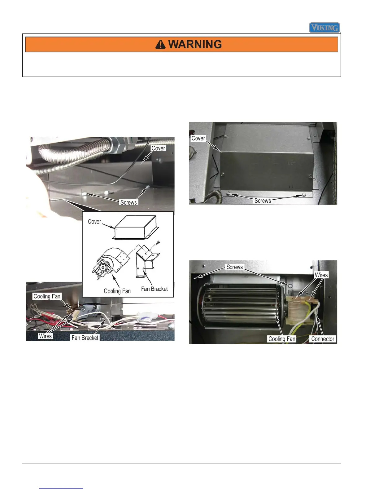
Cooling Fan Removal
(VGSC536 Only)
Condition Requirements:
Main Top Removed
1. Remove screws and cover from range.
2. Mark and disconnect wires from cooling fan.
3. Remove screws and cooling fan from fan bracket.
4. Reverse procedure for installation.
Note: Before installing main top and control panel,
verify that no unusual noise is present while
cooling fan is running.
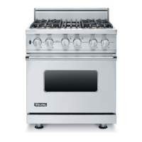
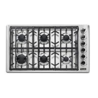
Cooling Fan Removal
(VGSC530 and VGSC548)
Condition Requirements:
Main Top Removed
1. Remove six screws and cover from range.
2. Mark and disconnect wires and connector from
cooling fan.
3. Remove two screws and cooling fan from range.
Note: Component tray may need to be removed in
order to access one of the screws that secure
cooling fan to range.
4. Reverse procedure for installation.
Note: Before installing main top and control panel,
verify that no unusual noise is present while
cooling fan is running. The cooling fan can
be forced on by disconnecting the oven RTD
connector (P15) on the control board.