21
C
D
A
e
f
d
a
b
c
d
c
g
± 1°
max
h
g
d
c
e
b
f
a
c
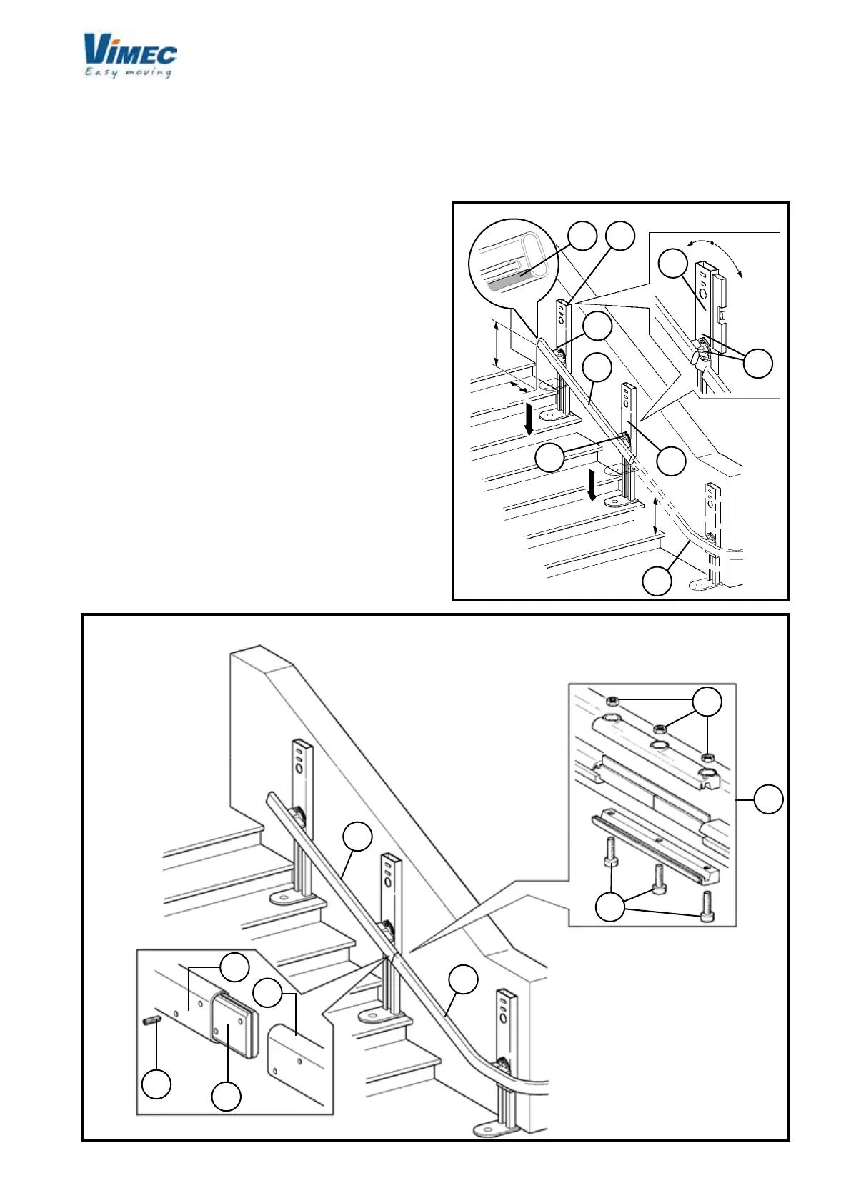
N.B.: Check that the part of the lower rail (Fig. 8/g)
on which the brushes operate is clean, and remove
any dirt if necessary.
WARNING: The rail xing screws (Fig. 7/a) must be
tightened to a torque of 9-10 daNm.
- Use the assembly markings (Fig. 3/b) to identify the
section of rail with feet (Fig. 8/a) to be placed just
above the bend just installed (Fig. 8/b).
- Position the rail correctly for installation (Fig. 8/a),
referring to the dimensions shown in the installation
drawing (example Fig. 5), extract the feet and lightly
tighten just one bolt (Fig. 8/c) for each connection
xture (Fig. 8/d).
- Fit the joint plates (Fig. 9/e) into the tubular rail (Fig.
9/a) and lightly tighten the rst 2 dowels (Fig. 9/f).
- Place the lower section of rail (Fig. 9/b) in position, t
the other dowels and tighten to a torque of 4-5 daNm
after checking that the tubular rails are correctly ali-
gned and there is no gap between the rail sections.
Fit the busbar connection joint (if any) as shown (Fig.
9/d) after checking that the components are clean.
- As already done with the bend, install the connection
xtures (Fig. 8/e) in perfectly vertical position, by
tightening both xing screws (Fig. 8/f) after adjustment.
- Install all the remaining rail sections except the last
one as previously described, all the way down to the
bottom of the staircase.
FIG.8
FIG.9
± 1°
max
In order to make assembly for wall xing easier (Fig.
10/a), it is advisable the use of special test feet (Fig.
10/b) (contact Vimec’s assistance since they are
excluded from the supply) to be plugged into the rail
instead of the intermediate connections (about 1-2 per
each ramp).
 Loading...


