40
a
40
a
a
c
b
d
e e
40
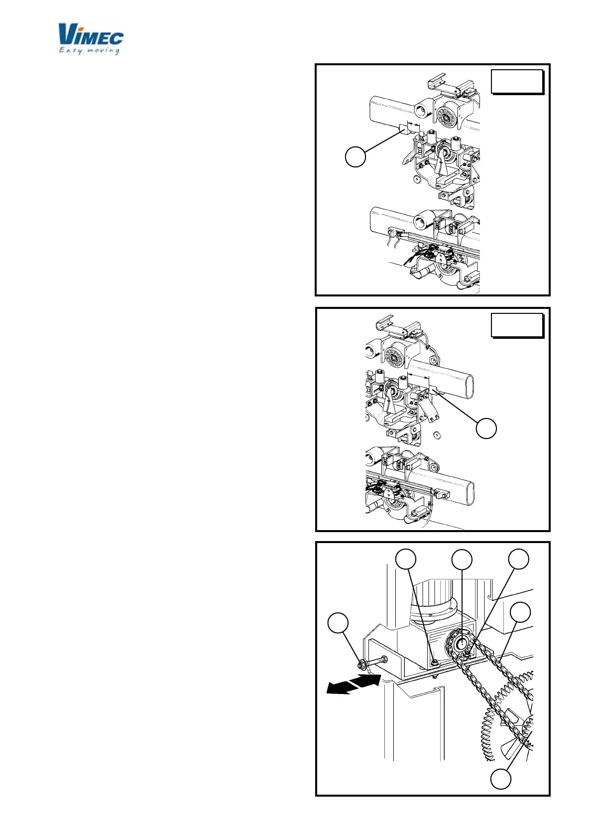
18) CHECKING THE POSITION OF THE OVER-RUN
DEVICE CAM AND PLATES
Before nal testing of the stairlift, check that the limit
stop (Fig. 60/a-61/a) is correctly positioned.
This position is correct if the dimensions are as shown
in the drawings in Fig. 60 and 61.
19) STRETCHING THE CHAIN
Stretch the chain (Fig. 62/b) by undoing the nuts (Fig.
62/e) and screwing down the hexagon (Fig. 62/a).
Take care not to apply excessive tension, as this will
mean too much strain on the drive shafts (Fig. 62/c and
Fig. 62/d). Tighten the nuts (Fig. 62/e) rmly when done.
20) FINAL TESTING
Supply power to the system and perform the fol-
lowing functional checks:
- Load test:
- Load the stairlift with 1.1 times the rated load stated
on the nameplate.
- Send the stairlift up and down several times, checking
its stability on the rail.
- Final testing for stairlifts with sections of rail ha-
ving gradient of less than 20°:
- Move the stairlift to the area with gradient of more than
25° and check that the cam drive roller is 0.5÷1.5 mm
from the cam (see Fig. 64).
- If the roller has to be moved towards or away from the
cam, remove the bracket (Fig. 67/a) and turn the clutch
wheel hub (Fig. 67/b) using the spanner provided (Fig.
67/c). After adjustment (30 daN/m) t the bracket (Fig.
65/a) and x the two screws (Fig. 67/d) with 243 loctite.
- Then move the stairlift to the area with gradient of
less than 20°, and place a weight of 250 kg on it with its
centre of gravity 150 mm from the edge (see Fig. 63).
- Check that the stairlift does not tilt by more than 2°.
- Preliminary checks
Perform the checks described in point 6.1 on page 8
of the Use and Maintenance Manual.
- Safety gear test
Test the safety gear as described in Section 10.1, point
“d”. (This test must be carried out with no load on the
stairlift).
- Checking the interlocking of the platform with
independent or retractable arms (manual platform)
- Check that as long as the down side bar is in the rest
position the platform remains locked, whether in the
working or the rest position.
FIG.60
UPPER
FLOOR
LOWER
FLOOR
FIG.61
FIG.62
 Loading...


