27
a
a
-
b
-
c
d
2
1
2
3
3
3
a
b
1
2
3
2,5
6,0
4,5
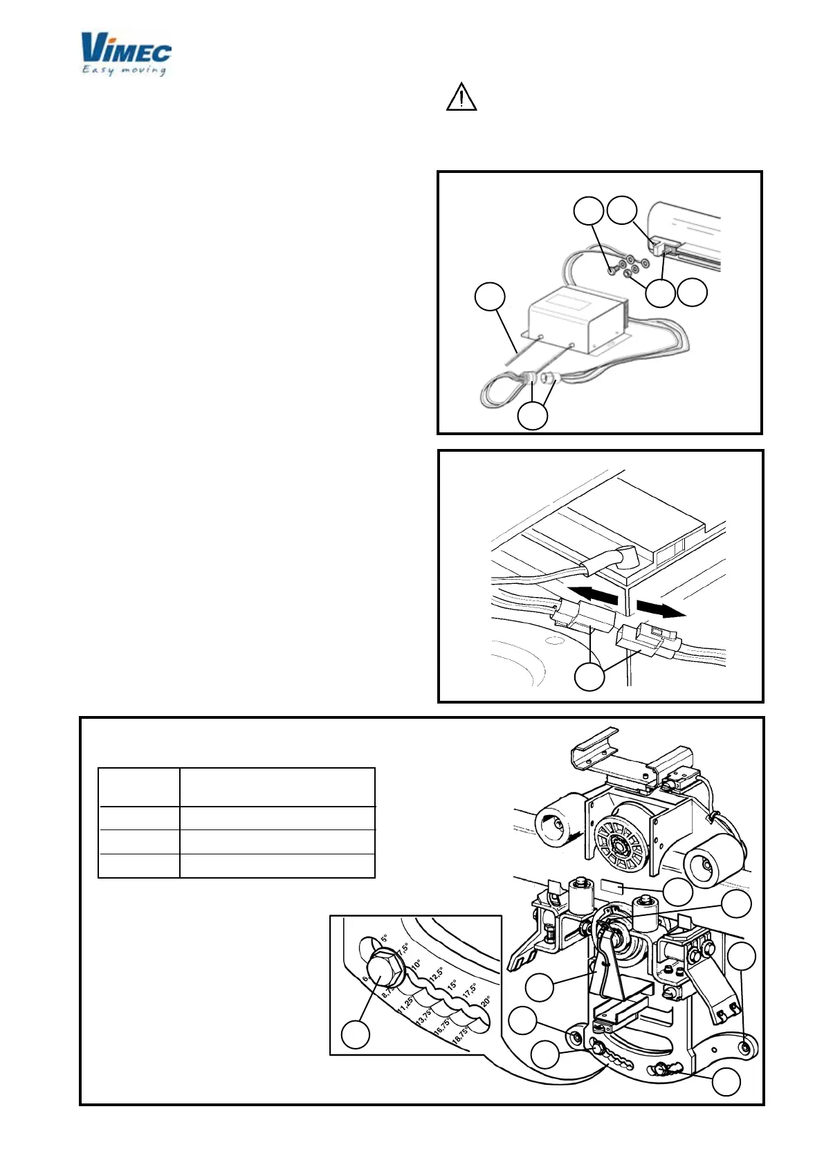
6) CONNECTING THE POWER SUPPLY UNIT
- Connect the cables (positive and negative) to the
busbar terminal provided, xed to the rail (Fig. 27/a-
Fig. 27/b).
- If the charge station is installed, connect the cables
leading from the station direction to the power supply
unit cables.
- Connect the 230 V 50 Hz power supply to the power
socket (Fig. 27/c).
- After installation, power up the system by connecting
the plug (Fig. 27/d).
- Connect the battery connector on the stairlift (Fig. 28)
and turn the on-off key on the casing to ON (Fig. 9/m
in use and maintenance manual). Once the stairlift has
been switched on, remove the key and keep it with the
documentation, the manual operation handwheel and
the bar release Allen key.
7) CONNECTING THE INSTALLATION ENGINEER’S
CONTROL PANEL
- Disassemble the casing (Fig. 29/b) by unscrewing the
xing screws and connect the console (Fig. 29/a) to the
connector provided.
- Access the “Position” subroutine.
- Press “Enter”.
- Type the “Password”.
- From the “Control from console” menu.
- Press “Enter”.
- “UP” to ascend, “DOWN” to descend.
- Temporarily t the magnet to the rail (Fig. 26/a) in
line with the home oor recognition sensor (Fig. 26/b).
Then press the UP button once to acquire the home
oor position and allow the stairlift to move.
FIG.28
FIG.27
FIG.26
WARNING: all safety devices are deactiva-
ted (the operator is responsible for ensuring safety).
DRIVING TORQUE
(daN X m)
POS.
 Loading...


