25
c
d
b
a
c
f
e
d
a
a
a
+
-
15
300
Ø10
20
FIG.20
FIG.19
When assembly of the rail is complete, for stairlifts
with constant gradient of less than 20°, check the
gradient of the entire rail (maximum permitted error
1°) before putting the stairlift into operation (see
Fig. 27).
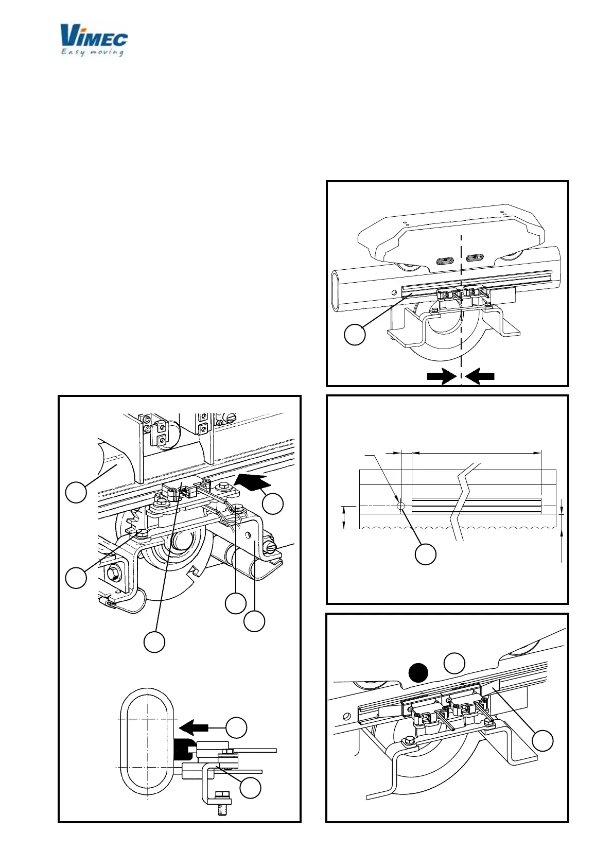
5) POSITIONING THE CHARGING STATION (if ap-
plicable)
- First position the stairlift where you wish it to stop.
This applies both to the top and bottom stops and to
the intermediate stops. In the case of the rst stop (the
lowest) or last stop (the highest), the aluminium prole
that holds the recharging contacts (Fig. 20a) should
already be xed to the rail.
- In the case of an intermediate stop, position the stai-
rlift at the stop and use the biadhesive tape provided
to x the contact prole to the lower rail so it is centred
with respect to the brushes (see Fig 20). Respect the
measurements in (Fig. 21) when positioning the prole.
If there is no hole for the power cables to pass through
near the intermediate stop, make a 10 mm diameter
hole as shown in (Fig 21/a).
FIG.21
FIG.22
- Insert the charging shoes in the contact prole so
that the negative pole (black wire) is ALWAYS to the
left, and the positive pole (red wire) is to the right
(Fig. 22), when looking at the rail from the rear. The
charging shoes must have the slanting side (Fig.
22/a) facing so that the contacts on the carriage
can easily slide onto them. Slide the charging guide
shoes along the prole to centre them perfectly
with the brushes.
 Loading...


