22
b
a
a
c
a
b
c
a
b
e
d
a
b
c
FIG.10
FIG.11
FIG.13
FIG.12
0±1
mm
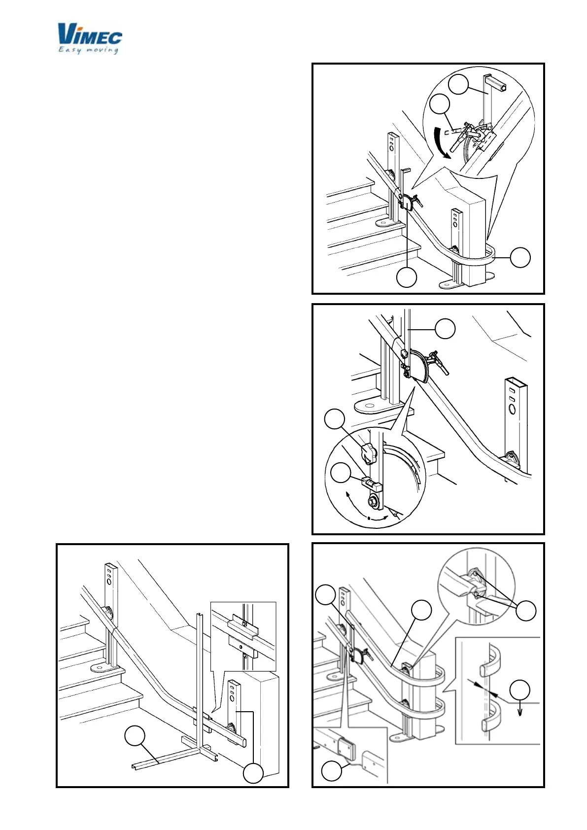
N.B.: The connection (Fig. 10/a) must be secured to
the wall before test operation of the stairlift.
3) INSTALLING THE UPPER RAIL
- Place the spacers (Fig. 11/a) (order them from the
Vimec service department since they are not included
in the supply package) at each end of the rst section
of rail installed (Fig. 11/b) (bend) and lock them rmly
in position by turning the lever as shown (Fig. 11/c).
- Undo the handwheel (Fig. 12/a) and use a spirit level
(Fig. 12/b) to position the supporting arm (Fig. 12/c)
perfectly vertical. After adjustment, tighten the han-
dwheel rmly (Fig. 12/a).
- Place the upper rail (Fig. 13/a) on the spacers (Fig.
13/b) just tted, and after checking that the com-
ponents are vertical (Fig. 13/c) tighten the screws
rmly (Fig. 13/d).
WARNING: The rail xing screws (Fig. 13/d) must
be tightened to a torque of 6-7 daNm.
- Install all the remaining sections of rail except the
last one as just described, down to the bottom of the
staircase. If supplied, to proceed with rail connecting,
t the charging station cable (Fig. 13/e) in the lower
guide.
- After assembly, use the black paint supplied to repair
any chips on the rails and seal the screws (Fig. 9/g)
and nuts (Fig. 9/h) of the busbar joint (where present)
with silicone.
 Loading...


