23
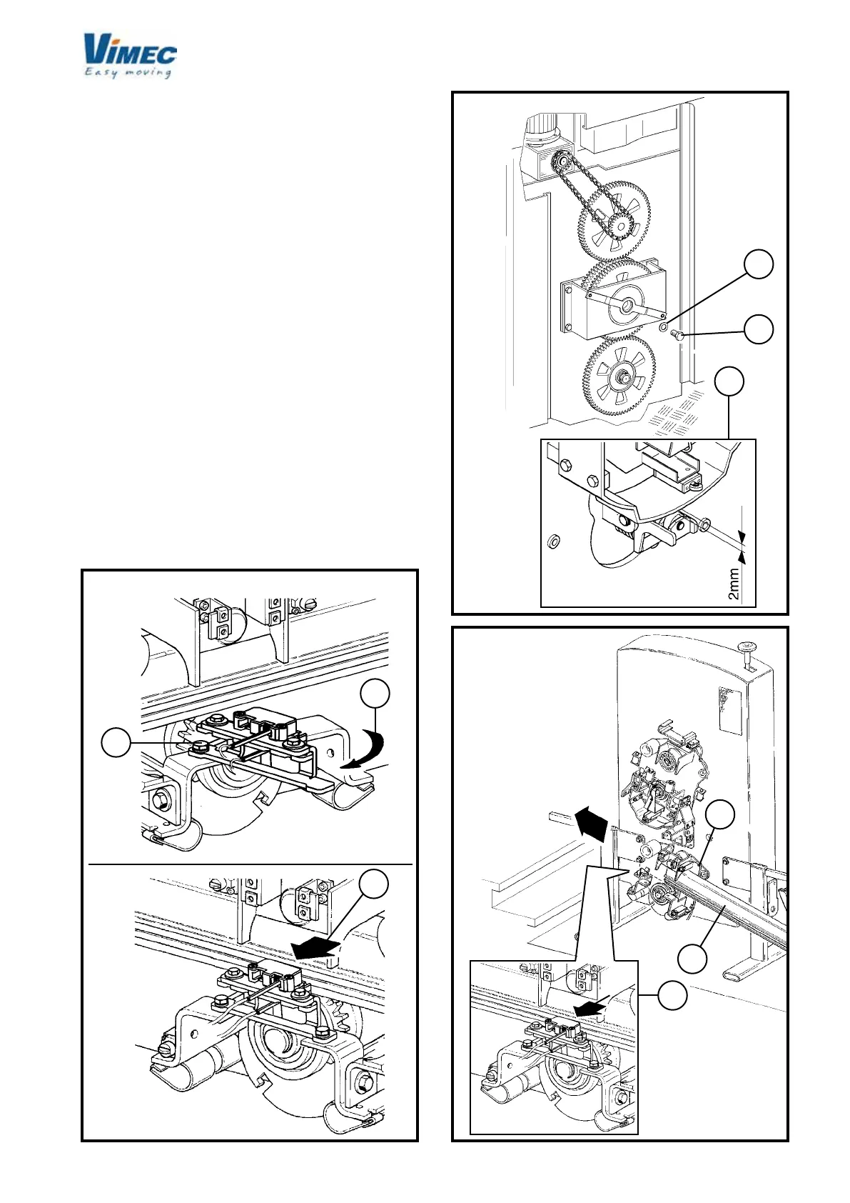
a
b
c
c
b
a
b
a
c
4) INSTALLING THE CARRIAGE
- Place the main structure, complete with carriages, in
the parking area at the bottom oor.
- Screw the M10x30 screw (Fig. 15/a) with washer
(Fig. 15/b) onto the clutch plate assembly (if installed)
in order to release the upper carriage from the clutch
assembly. The gap is correct when the clutch assembly
cam is about 2 mm from the carriage (Fig. 15/c).
- Unscrew the brush-holder xing screw (Fig. 14/a) and
turn it in the direction shown by the arrow (Fig. 14/b) or
pull the brushes backwards (Fig. 14/c) while tting the
tubular rail into the bottom carriage.
N.B.: During the steps described below, grease the
guide shoes and then take special care to position them
correctly (Fig. 17/f - 18/e).
- Insert the bottom tubular rail (Fig. 16/a) into the bottom
tilting device (Fig. 16/b) remembering to pull back the
brushes (Fig. 14/c) if they have not been turned around
(Fig. 14/b).
- Insert the bottom tubular rail (Fig. 17/a) into the tilting
device (Fig. 17/b), checking that the drive sprocket
teeth (Fig. 17/e) engage inside the holes correctly, to
the point where the rail is joined to the section installed
earlier (Fig. 17/c).
FIG.14
FIG.16
FIG.15
SOLUTION "A"
SOLUTION "B"
 Loading...


