29
d
b
d
b
c
a
c
a
b
d
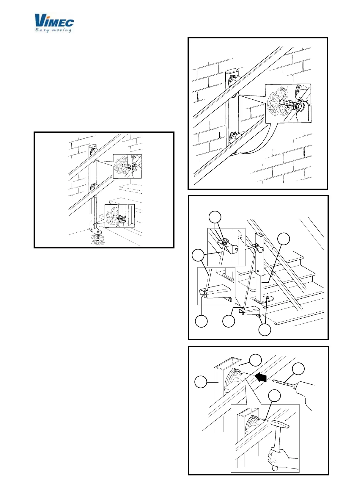
8) FIXING THE CONNECTION FEET
After performing a stairlift trial run to make sure that
everything has been assembled correctly, the next step
is to x the mounting feet to the oor and the connec-
tions to the wall (where possible, in the latter case).
Depending on the type of foot which appears in the
installation drawing, t the feet rmly as shown by the
examples below (Fig. 31-32-33).
If the feet are xed to the step (Fig. 34), drill the holes in
the steps and x using the screws (Fig. 34/a) supplied.
After the xing operation, tighten the screws hard (Fig.
34/b).
If the feet have a hinged support (Fig. 33), drill the
holes in the xing points and x using the screws (Fig.
33/a) supplied.
Tighten the foot (Fig. 33/c) by tting the threaded bar
into the holes provided (Fig. 33/b) and screwing down
the nut and lock-nut (Fig. 33/d) until the tension is
correct.
To ensure that the angle of the rail (Fig. 35/a) does not
change over time, check again that all parts have been
assembled correctly and then drill a hole (Fig. 35/b) in
the connecting joint (Fig. 35/c) and t a locking pin (Fig.
35/d) into the hole.
FIG.32
FIG.33
FIG.35
N.B.: Move the stairlift up to the 1st rigid connection and
if it is not horizontal, screw down the M10x30 screw
(Fig. 15/a) with washer (Fig. 15/b) onto the clutch
assembly to release the upper tilting device from the
clutch assembly. The gap is correct when the clutch
assembly cam is about 2 mm from the carriage (Fig.
15/c).
- Move the stairlift up a short way to allow it to settle
back into position.
- Undo the screw (Fig. 15/a) and its washer (Fig. 15/b)
to re-engage the clutch plate assembly with the tilting
device.
FIG.31
 Loading...


