20
a
b
C
D
A
a
a
d
a
b
a
d
c
A
B
160
FIG.3
FIG.4
FIG.6
FIG.7
FIG.5
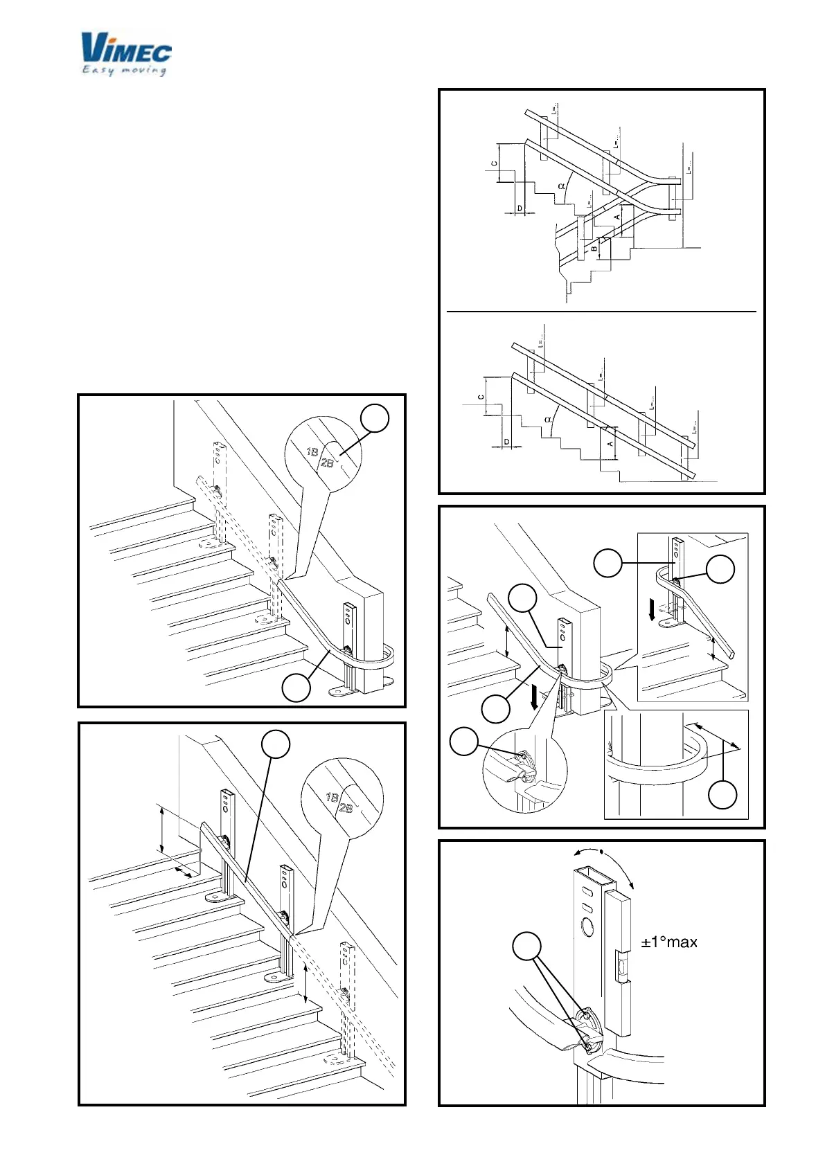
2) INSTALLING THE LOWER RAIL
- Use the assembly markings (Fig. 3/b) to identify the
rst section of rail, with the bend (Fig. 3/a) starting from
the top oor.
N.B.: If there are no bends, nd the rst straight section
(Fig. 4/a) starting from the top.
- Place the bend in the installation point (Fig. 6/c).
- Referring to the dimensions shown in the installation
drawing (example Fig. 5) extract the feet and lock them
lightly in position with just one screw (Fig. 6/a) for each
connection device (Fig. 6/d).
N.B.: First connect up all sections; only x the feet
afterwards.
N.B.: Make sure that the outer edge of the rail is 160
mm (Fig. 6/b) from the banister or dividing wall.
- Set the bend connection xtures perfectly vertical (Fig.
7) and tighten both the xing screws once adjustment
is complete (Fig. 7/a).
 Loading...


