24
c
f
b
e a
g
g
d
f
d
cb
e
e
a
f
g
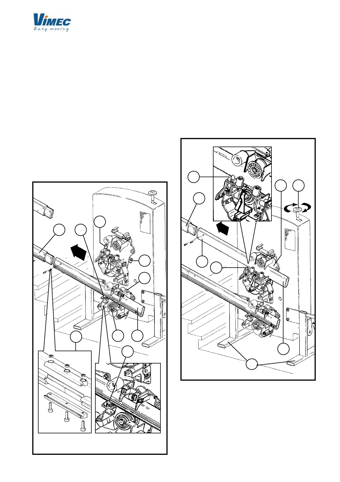
FIG.17
- Make the joint in the busbar (Fig. 17/d) as described
earlier.
- Fit the upper rail (Fig. 18/a) into the tilting device (Fig.
18/b) and use the upper handwheel (Fig. 18/c) to
insert it until a joint is formed with the rail (Fig. 18/d)
installed earlier.
N.B. In the event of excessive play between the
“straight rail roller” (Fig. 17/g) and the rail (Fig.
18/g), replace the roller with another of larger
diameter, supplied in the package.
- If you turned the brush-holder unit around earlier (Fig.
19) turn it back into the original position.
- Version with busbar
- Press the assembly (Fig. 19/c) by hand in the direction
shown by the arrow (Fig. 19/d) until both brushes are
retracted by at least 5 mm.
- Keeping the assembly (Fig. 19/c) pressed against
the rail (Fig. 19/e), rmly tighten the screws (Fig. 19/a
and 19/f).
- Version without busbar
- Put the brush-holder unit back in its initial position,
reassembling the xing screw.
WARNING: Do not allow the connection wires to
project beyond the edge of the brush-holder, to
allow the protective casing to close correctly.
- Undo the screw (Fig. 15/a) and its washer (Fig.
15/b) and remove them from the stairlift to re-
engage the clutch plate assembly with the tilting
device and remove the supporting feet (Fig. 18/f).
FIG.18
 Loading...


