35
a
b
125
c
ab
a
a
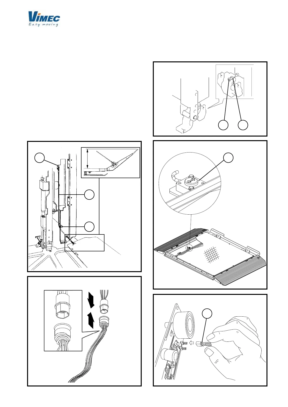
f) Connect the wires (Fig. 49/c) to the side guard boards,
passing them around the pin (Fig. 49/a).
If the guards are not opened or closed correctly, adjust
to the specied position using the register fork (Fig.
49/b).
g) Close the platform using the cover plate and the
xing screws provided.
h) Remove the wedge and plastic clamp (Fig. 46/c,d)
used to keep the platform horizontal during adjustment
from the platform supports.
i) Tighten the nut and lock-nut with a driving torque of
4 daN ± 0.1 (Fig. 51/a,b).
l) Plug in the connectors J14 - J16 (Fig. 50).
CLINOMETER RESET
The 1250x800 and 1050x900 standard platforms, and
FIG.50
FIG.49
other platforms upon customer’s request, are equipped
with a clinometer to check any footboard overloads
(Fig. 52/a).
Once the platform is completely installed, it must
FIG.51
FIG.52
FIG.53
 Loading...


