Chapter 3 Hardware description Manual VIPA System 300V
3-14 HB130E - CPU - Rev. 11/50
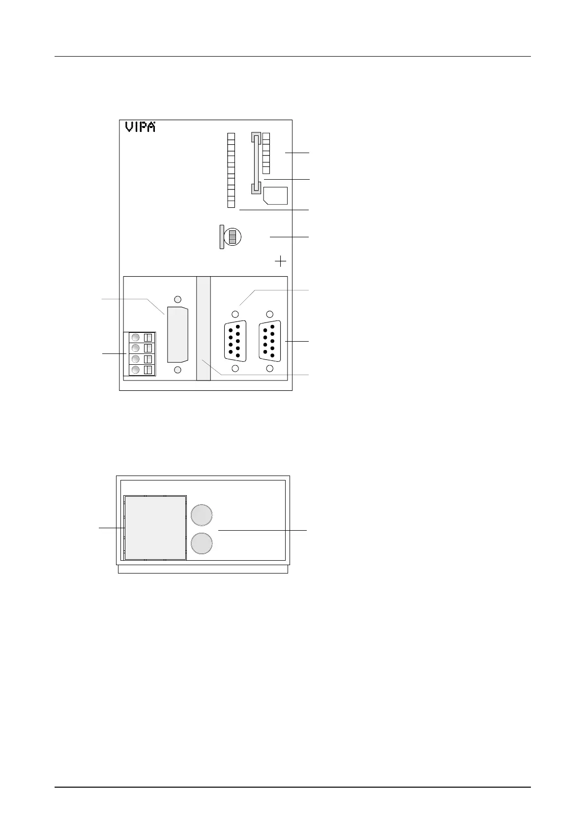
For later expansions there are places for an Ethernet slot res. Switch slot,
keyboard and mouse (as PS2-Connection) on the underside of the front
flap:
CPU 31xDPM
31x-2DP01
Underside view
PWR
RUN
STOP
SF
FRCE
MMC
DESL
MMC
RUN
STOP
MRES
PLC
X1
VIPA 314-2DP01
X2 X3
PS MP I PB-DP
CPU314DPM
X2
3
4
DC 24V
+
-
+
-
1
2
6
5
3
4
7
8
9
RUN
ERR
DE
IF
PB-M
2
[1] Clipping for Ethernet slot
res. Switch
[2] Clipping for keyboard res.
mouse PS2 slots
1
2
[1] LEDs of the integrated Profibus D
[2] MMC slot
[3] LEDs of the CPU part
[4] Operating mode switch CPU
The following components are
under the front flap
[5] Clipping for DVI slot
[6] Slot for DC 24V Power supply
[7] MP
2
I interface
[8] RS485 Profibus interface
[9] Clipping for CompactFlash slot