Manual VIPA System 300V Chapter 4 Deployment CPU 31x
HB130E - CPU - Rev. 11/50 4-7
Addressing
To provide specific addressing of the installed peripheral modules, certain
addresses must be allocated in the CPU.
The CPU contains a peripheral area (addresses 0 ... 1023) and a process
image of the inputs and the outputs (for every address 0 ... 127).
When the CPU is initialized, it automatically assigns peripheral addresses
to the digital input/output modules starting from 0.
When no hardware project engineering is available, analog modules are
stored at the automatic address allocation on even addresses starting with
128.
In the hardware configurator from Siemens you may parameterize maximum
up to 8 modules per row. When using the System 300V CPUs from VIPA you
may control up to 32 modules by distributing the modules you want to
parameterize on the first 8 Plug-ins. Although the modules that are behind on
the profile rail are not visible, they are included into the addressing range of
the CPU by means of the automatic addressing.
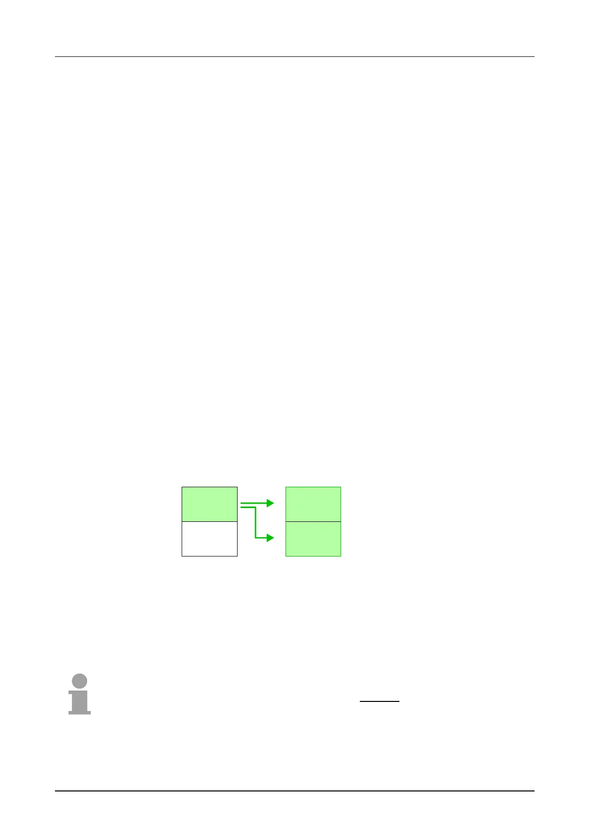
The signal states of the lower addresses (0 ... 127) are additionally saved
in a special memory area called the
process image.
The process image this divided into two parts:
• process image to the inputs (PAE)
• process image to the outputs (PAA)
Peripheral area
0
.
.
.
127
128
.
.
.
1023
Process image
0
.
.
.
127
0
.
.
.
127
Inputs
PAE
Outputs
PAA
Digital modules
Analog modules
The process image is updated automatically when a cycle has been
completed.
You may access the modules by means of read or write operations on the
peripheral bytes or on the process image.
Note!
Please remember that you can access different modules by means of read
and write operations on the same address.
Digital and analog modules have separate address ranges at the automatic
address allocation.
Digital modules: 0 ... 127, Analog modules: 128 ... 1023
Automatic
addressing
Up to 32 modules
in one row
Signal states in
the process image
Read/write access