Chapter 4 Deployment CPU 31x Manual VIPA System 300V
4-8 HB130E - CPU - Rev. 11/50
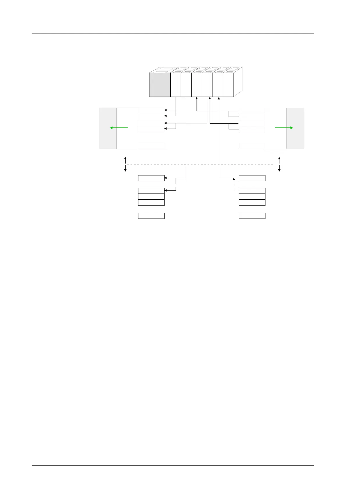
The following figure illustrates the automatic address allocation:
CPU 31x
Input byte 0
.
.
.
128
.
.
.
143
144
145
.
.
.
1023
rel. Adr. Peripheral area
DI 16xDC24V
AI 8x12Bit
DO 16xDC24V
DIO 16xDC24V
AO 4x12Bit
analog
digital
.
.
.
.
.
.
.
.
.
Input byte 1
Input byte 2
Input byte 3
Input byte 127
Input byte 0
Input byte 15
Input byte 16
Input byte 17
Input byte 1023
Output byte 0
.
.
.
Peripheral area rel. Adr
.
.
.
.
.
.
Output byte 1
Output byte 2
Output byte 3
Output byte 127
Output byte 0
Output byte 7
Output byte 8
Output byte 9
Output byte 1023
0
1
2
3
.
.
.
127
128
.
.
.
135
136
137
.
.
.
1023
analog
digital
PAA
0
1
2
3
.
.
.
127
PAE
Slot no.: 1 2 3 4 5 6
You may change the address allocation with the help of the SIMATIC
manager from Siemens at any time. This allows you to get also analog
modules into the process image area (0 ... 127) and digital modules above
address 127.
The preparation for the project engineering and the approach are
described on the following pages.
Example for the
automatic address
allocation
Change address
allocation by
project
engineering