Chapter 3 Hardware description Manual VIPA System 300V
3-16 HB130E - CPU - Rev. 11/50
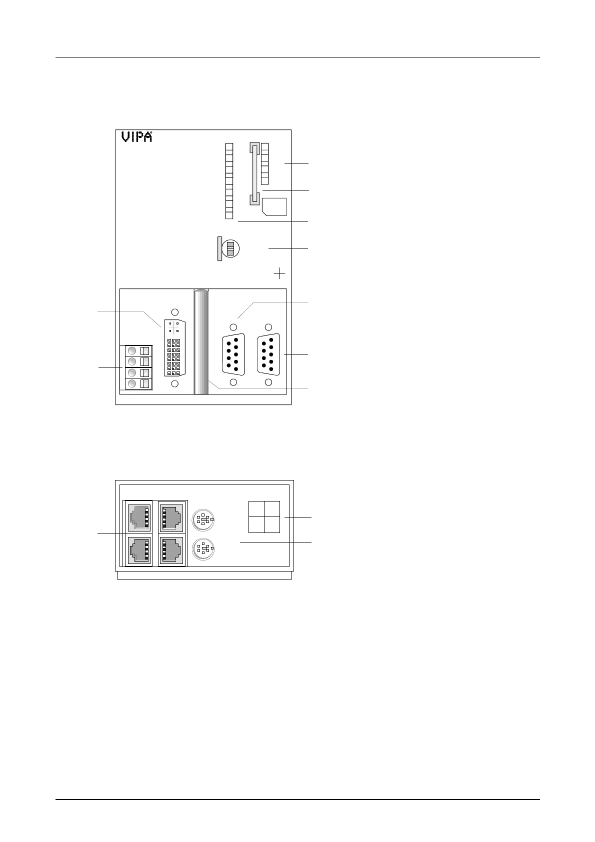
The connections for Ethernet, keyboard and mouse are beneath a front
flap that you may raise.
CPU 31xNET
31x-3DP01
Underside view
PWR
RUN
STOP
SF
FRCE
MMC
DESL
RUN
ERR
DE
IF
MMC
RUN
STOP
MRES
PLC
X1
VIPA 315-3DP01
PB-M
X5
X2 X3
PS DVI CF PB-DP
CPU315NET
X2
3
4
DC 24V
+
-
+
-
1
2
6
5
3
4
7
8
9
MP I
2
[1] LEDs of the integrated
Profibus DP master
[2] MMC slot
[3] LEDs of the CPU part
[4] Operating mode switch CPU
The following components are
under the front flap
[5] DVI slot
[6] Slot for DC 24V Power supply
[7] MP
2
I interface
[8] RS485 Profibus interface
[9] CompactFlash slot
[1] 4port Switch for twisted pair
connection to the Ethernet
[2] Assignment of the 4port
Switch
[3] Jacks for keyboard res.
mouse
X4
KBD
MOUSE
No.1 No.3
No.2 No.4
X4-NET
X6
X7
1
3
2