Chapter 3 Hardware description Manual VIPA System 300V
3-18 HB130E - CPU - Rev. 11/50
The recent CPU includes the following jacks res. plugs:
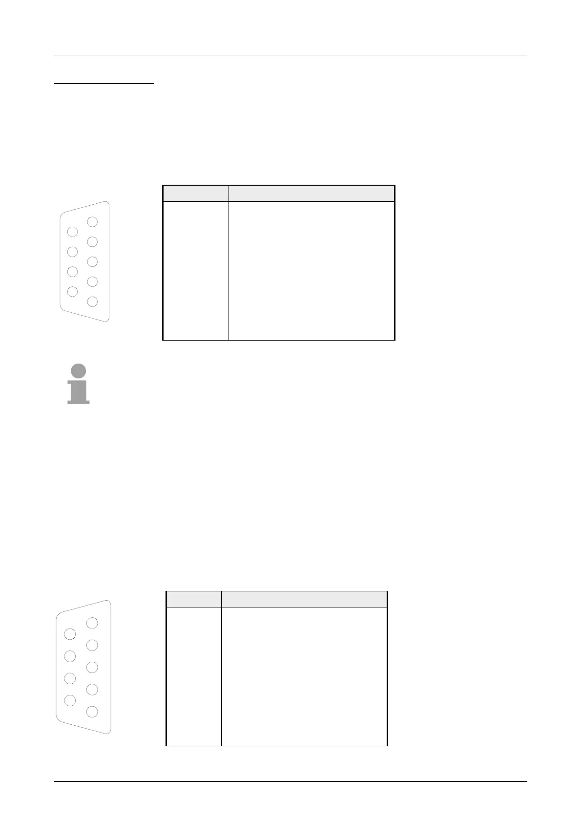
Via the 9pin RS485-interface you link up the integrated Profibus-DP master
to your Profibus network. The RS485 jack has the following pin
assignment:
9pin jack
Pin Occupation
1 Shield
2 n.c.
3 RxD/TxD-P (Line B)
4 RTS
5 M5V
6 P5V
7 n.c.
8 RxD/TxD-N (Line A)
9 n.c.
Note!
Please make sure to activate the terminating resistors at the bus ends!
The MP
2
I interface handles the data exchange between CPU and PC. Via
a bus communication you may transfer applications and data between the
CPUs that are connected via MPI.
For a serial transfer from your PC you normally need a MPI transducer.
Alternatively you may use the "Green Cable" (Order No.: 950-0KB00). from
VIPA, that allows a serial connection without transducer. The "Green
Cable" may only be used directly and exclusively at CPUs with MP
2
I
interface. Please also regard the hints in the chapter "Deployment CPU
31x"!
The MP
2
I jack has the following pin assignment:
9pin jack
Pin Assignment
1 reserved (do not connect)
2 M24V
3 RxD/TxD-P (Line B)
4 RTS
5 M5V
6 P5V
7 P24V
8 RxD/TxD-N (Line A)
9 n.c.
Jacks and Plugs
Profibus-interface
PB DP
MP
2
Interface
5
4
3
2
1
9
8
7
6
5
4
3
2
1
9
8
7
6