12
©
2005
Directed Electronics, Inc. all rights reserved
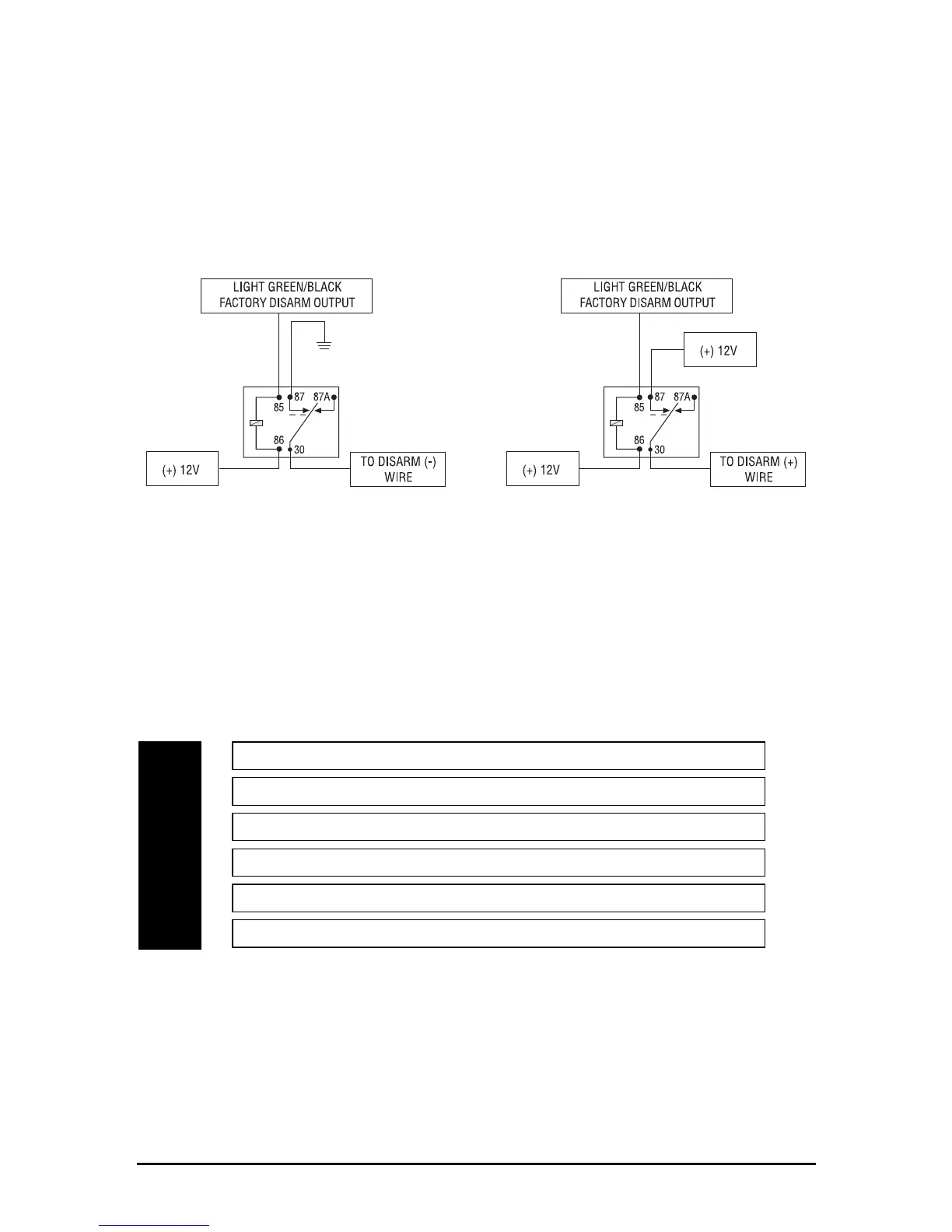
H2/6 LIGHT GREEN/BLACK (-) factory disarm output
This wire sends a negative pulse every time the alarm is disarmed or the optional remote start is
activated. This can be used to pulse the disarm wire of the vehicle's factory anti-theft device. Use a
relay to send a (-) or (+) pulse to the disarm wire as shown in the diagrams below. This also outputs
when Channel 2 is activated. This function is programmable ON/OFF.
RReellaayy ffoorr NNeeggaattiivvee ((--)) DDiissaarrmm WWiirree RReellaayy ffoorr PPoossiittiivvee ((++)) DDiissaarrmm WWiirree
Door Lock Harness Wire Connection Guide
Relay Harness Wiring Diagram
___
___
___
___
___
___
*NOTE: VIOLET and VIOLET/BLACK are common at fuse holder.
HH11 ccoonnnneeccttoorr cceennttrraall ddoooorr lloocckkiinngg
The system has door lock relays on-board, and can directly interface with most central locking
systems drawing 20 amps or less.
BLUE/BLACK Unlock #30 Common (Output)
VIOLET* Unlock #87 Normally Open (Input)
WHITE/BLACK Lock #87a Normally Closed
GREEN/BLACK Lock #30 Common (Output)
VIOLET/BLACK* Lock #87 Normally Open (Input)
BROWN/BLACK Unlock #87a Normally Closed
H1/10
H1/16
H1/17
H1/18
H1/19
H1/20
 Loading...