93
ВАРШ.201219.009РЭ
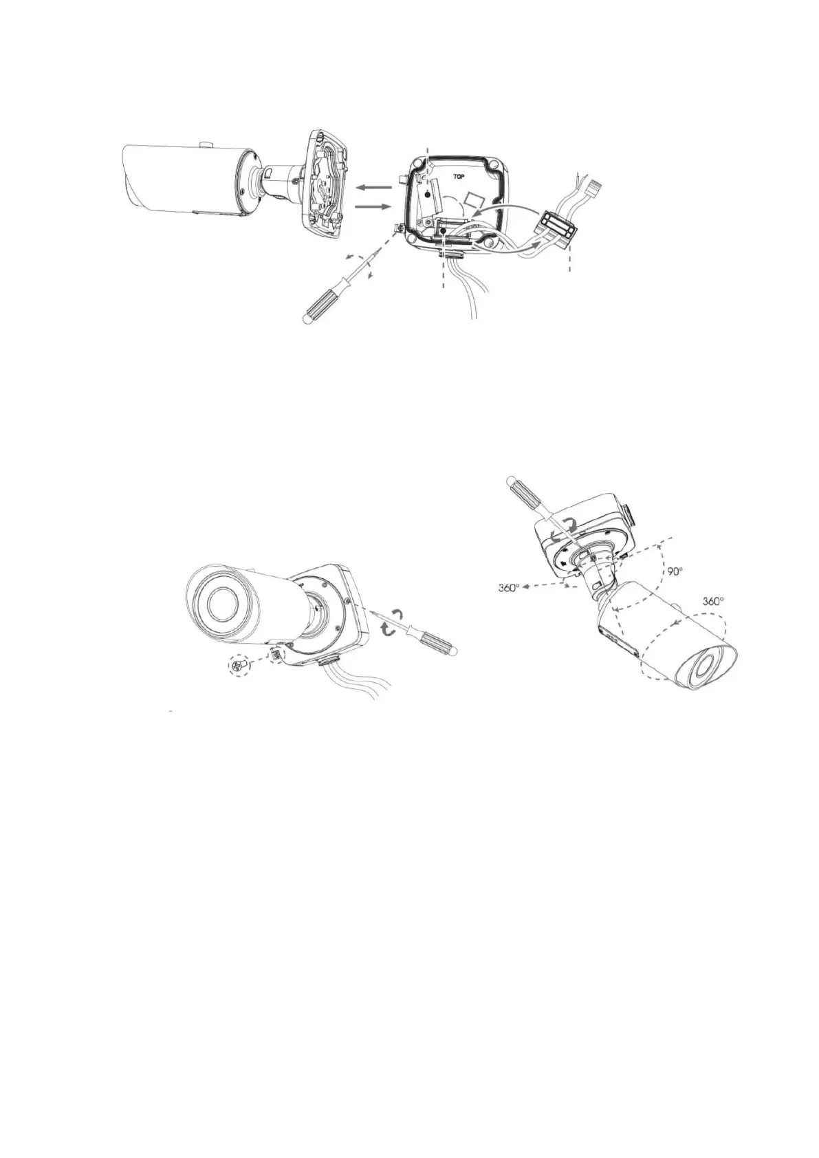
Step 3: Place the front cover at an angle of about 90 ° to the back cover. Pay attention to the
TOP marks. The TOP of the camera must be aligned with the TOP of the junction box;
Step 4: Adjust the length of the cables, connect them to the corresponding interfaces and fix
with the clamp. Close the junction box and tighten the screws. Please remember to install the rubber
plug when the holes are not in use;
Step 5: adjust the shooting direction and fix the set screw tightly.