96
ВАРШ.201219.009РЭ
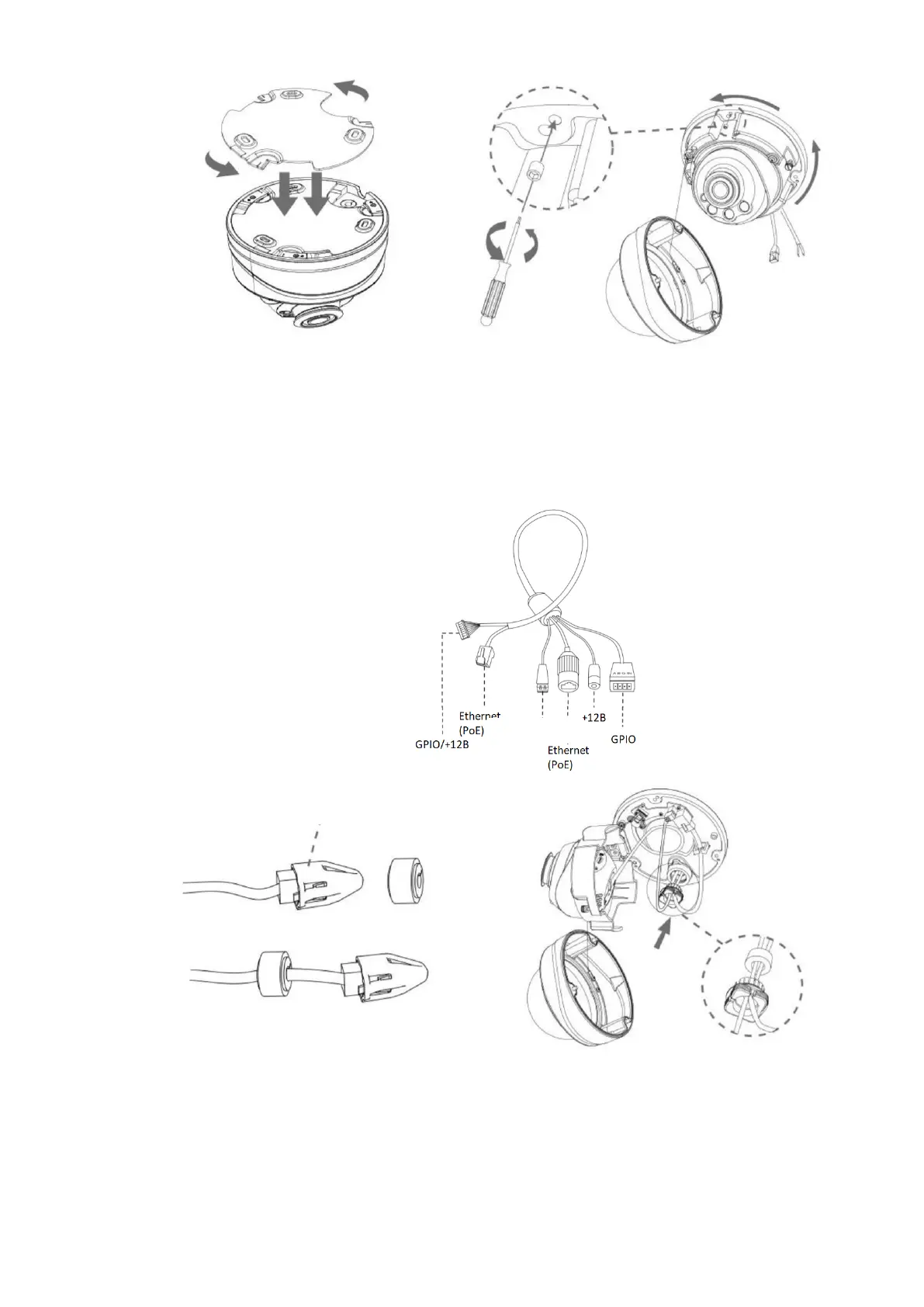
Step 4: Thread the cables through the white rubber ring and the black rubber plug in sequence
(place the punching cap on the Ethernet connector and thread the cable through the white rubber
ring from the large hole to the small one). Align the ring and plug, screw them into the cable entry
hole. Connect the cables to the corresponding connectors, then attach the camera body to the base;
Step 5: Loosen the clamping screw, adjust the camera lens in the desired direction. Tighten
the clamping screw to secure the lens;