VISUAL
TECHNOLOGY
INCORPORATED,
RAILROAD
AVENUE,
DUNDEE
PARK,
ANDOVER,
MA
01810
3. KEYBOARD AND CONTROLS
3.1
REAR
PANEL
SWITCHES
3.1.1 General
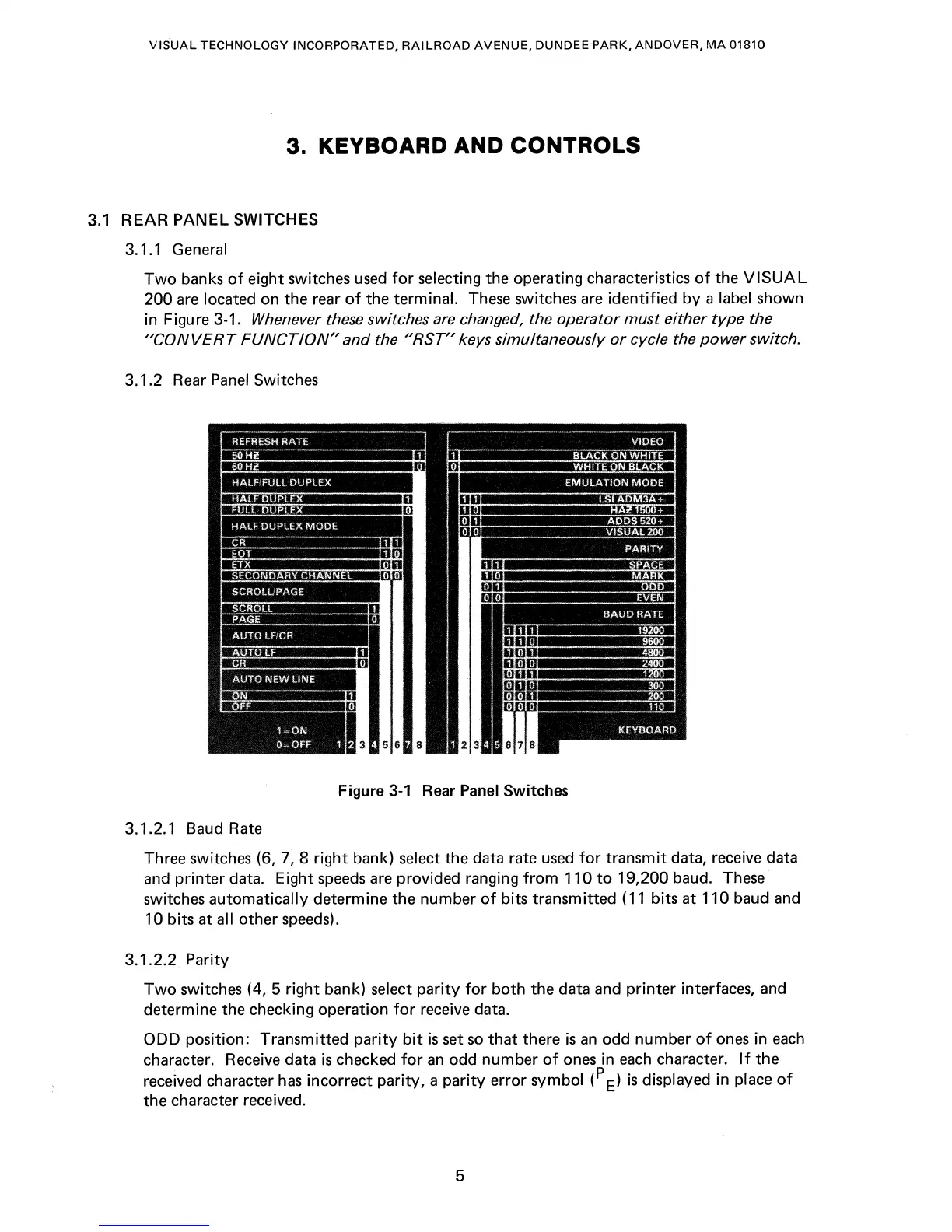
Two
banks
of
eight switches
used
for
selecting the operating characteristics
of
the
VISUAL
200
are
located on the rear
of
the terminal. These switches
are
identified
by
a label shown
in Figure 3-1.
Whenever these switches
are
changed, the operator
must
either
type
the
"CONVERT
FUNCTION"
and
the
"RST"
keys simultaneously or cycle the power switch.
3.1.2 Rear
Panel
Switches
Figure
3-1
Rear Panel Switches
3.1.2.1 Baud Rate
Three switches (6,
7, 8
right
bank) select the data rate
used
for
transmit data, receive data
and
printer
data. Eight
speeds
are provided ranging
from
110
to
19,200 baud. These
switches
automatically determine the number
of
bits transmitted
(11
bits at 110 baud and
10 bits at all
other
speeds).
3.1.2.2
Parity
Two
switches (4, 5
right
bank) select
parity
for
both
the data and
printer
interfaces, and
determine the checking operation
for
receive data.
ODD
position: Transmitted
parity
bit
is
set
so
that
there
is
an
odd number
of
ones
in
each
character. Receive data
is
checked
for
an
odd number
of
ones in
each
character.
If
the
received character
has
incorrect parity, a
parity
error symbol (p
E)
is
displayed in place
of
the character received.
5