VISUAL
TECHNOLOGY
INCORPORATED,
RAILROAD
AVENUE,
DUNDEE
PARK,
ANDOVER,
MA
01810
7. FIRST LEVEL MAINTENANCE
7.1
GENERAL
The
VISUAL
200 terminal
has
been
designedwith subassembly exchange
as
the prime mode
of
service. Fault isolation
is
provided in this section
to
identify
the failing subassembly.
Unless
otherwise noted the power cord should
be
disconnected before disassembly
of
the
terminal. Hazardous voltages may
be
present.
7.2
REAR
PANEL
The removal
of
the rear panel
will
allow the removal
of
the logic printed
circuit
board,
removal
of
the
TV
monitor
printed
circuit
board, and
access
to
the AC terminal block allow-
ing rewiring
from
110 volts
to
220 volts.
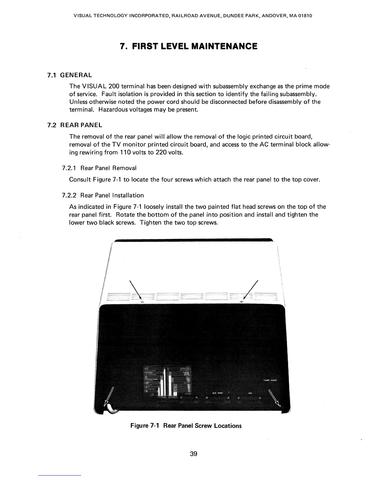
7.2.1 Rear
Panel
Removal
Consult
Figure
7-1
to
locate the
four
screws
which attach the rear panel
to
the
top
cover.
7.2.2 Rear
Panel
Installation
As indicated in Figure
7-1
loosely install the
two
painted
flat
head
screws
on the
top
of
the
rear
panel first. Rotate the
bottom
of
the panel
into
position
and
install and tighten the
lower
two
black screws. Tighten the
two
top
screws.
Figure
7-1
Rear
Panel
Screw Locations
39