VISUAL
TECHNOLOGY
INCORPORATED,
RAILROAD
AVENUE,
DUNDEE
PARK,
ANDOVER,
MA
01810
FULL
DUPLEX
+ 18 -
....
f-------i+
I CU R RENT
~------
.
SOURCE.
COMPUTER
TRANSMITTER
-17-.~---------------------------------
+
_
f------+~I
CURRENTI-
+21
~
~----------
SOURCE COMPUTER RECEIVER
-25-~~------------------~-------------+
HALF
DUPLEX
+ 18 -..
----------+-11
CU
R RENT
~------------
.
SOURCE.
COMPUTER
TRANSMITTER
-17~
+21
.----J
c:
COMPUTER RECEIVER
-25-~~-------------------------------+
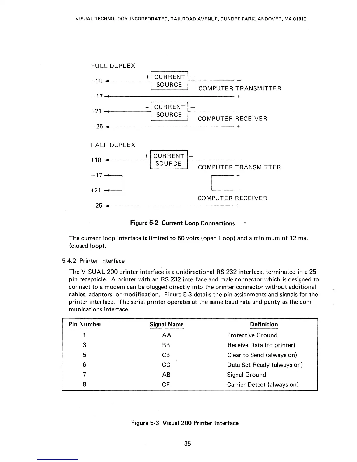
Figure 5-2 Current
Loop
Connections
The current loop interface
is
limited
to
50 volts (open Loop) and a
minimum
of
12
mao
(closed loop).
5.4.2
Printer Interface
The
VISUAL
200
printer
interface
is
a unidirectional
RS
232 interface, terminated in a 25
pin recepticle. A
printer
with
an
RS
232 interface and male connector which
is
designed
to
connect
to
a modem
can
be
plugged
directly
into
the
printer
connector
without
additional
cables, adaptors,
or
modification.
Figure 5-3 details the pin assignments and signals
for
the
printer
interface. The serial
printer
operates
at
the
same
baud rate and
parity
as
the com-
munications interface.
Pin Number Signal Name
Definition
1
AA
Protective Ground
3
BB
Receive Data
(to
printer)
5
CB
Clear
to
Send (always on)
6
CC
Data Set Ready (always on)
7
AB Signal Ground
8
CF
Carrier Detect (always on)
Figure 5-3 Visual
200
Printer Interface
35