VISUAL
TECHNOLOGY
INCORPORATED,
RAILROAD
AVENUE,
DUNDEE
PARK,
ANDOVER,
MA
01810
5.5 COMMUNICATIONS
INTERFACE
JUMPERS
5.5.1 General
There
are
four
jumpers W3, W4,
W5,
and
W6
which affect the pin and signal assignments on
the communications interface.
Normally the terminal
is
supplied
with
all
four
jumpers
installed
and
in most
cases
no modifications
are
required.
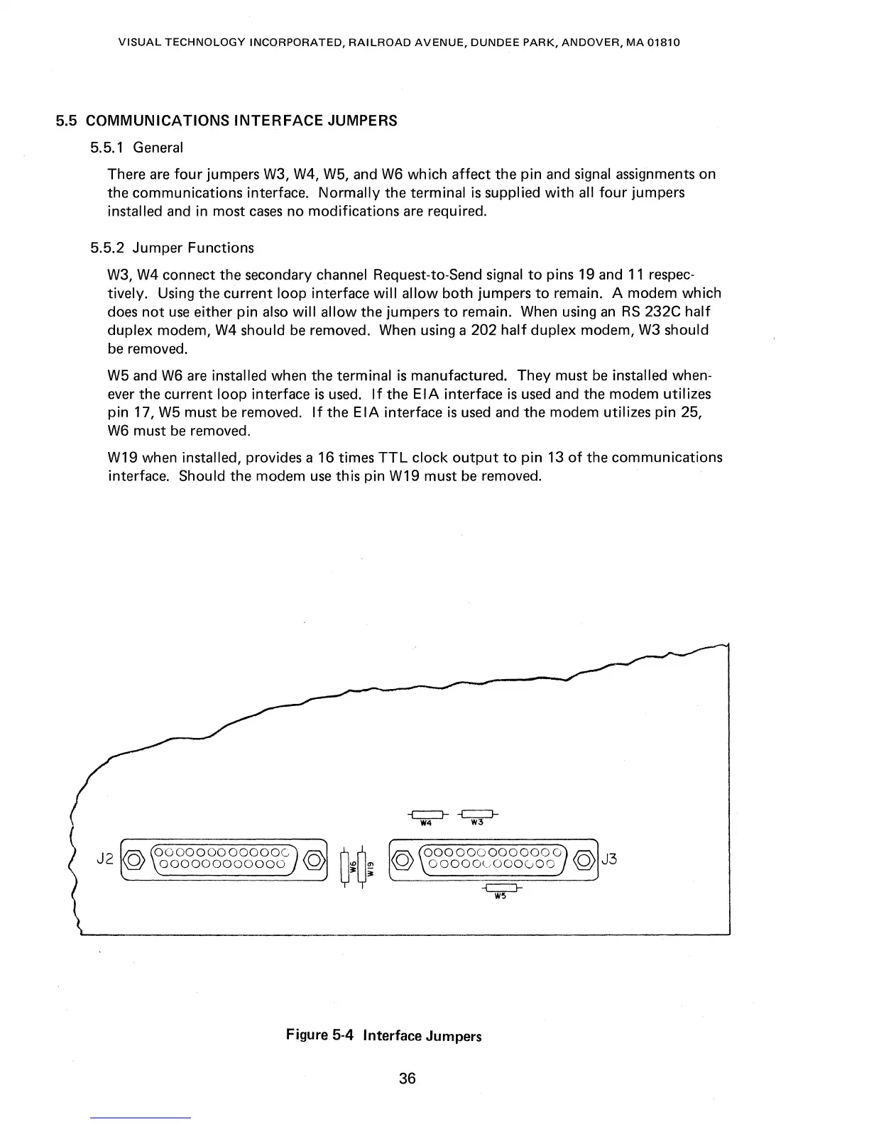
5.5.2 Jumper Functions
W3,
W4
connect the secondary channel Request-to-Send signal
to
pins 19 and
11
respec-
tively. Using the current loop interface
will
allow both jumpers
to
remain. A modem which
does
not
use
either pin
also
will allow the jumpers
to
remain.
When
using
an
RS
232C half
duplex modem,
W4
should
be
removed.
When
using a 202
half
duplex modem,
W3
should
be
removed.
W5
and
W6
are
installed when the terminal
is
manufactured. They must
be
installed when-
ever
the current loop interface
is
used.
If
the
EIA
interface
is
used
and the modem utilizes
pin 17,
W5
must
be
removed.
If
the
EIA
interface
is
used
and
the
modem utilizes pin 25,
W6
must
be
removed.
W19 when
installed, provides a 16 times
TTL
clock
output
to
pin
13
of
the communications
interface.
Should the modem
use
this pin W19 must
be
removed.
ooooooooooooc
000000000000
-c::::J--
-c::::J-
W4
W3
0000000000000
00000<.-,000000
Figure 5-4 Interface Jumpers
36