VISUAL
TECHNOLOGY
INCORPORATED,
RAILROAD
AVENUE,
DUNDEE
PARK,
ANDOVER,
MA
01810
the modem switches direction. With secondary channel operation the computer would
send
a break on the secondary channel and compel the terminal
to
immediately
exit
the
transmit mode. Break
can
also
be
sent
by
the terminal when the opposite condition
is
true.
5.4
COMMUNICATION
INTERFACE
PIN
1
2
3
4
5
6
7
8
11
12
13
17
18
19
20
21
25
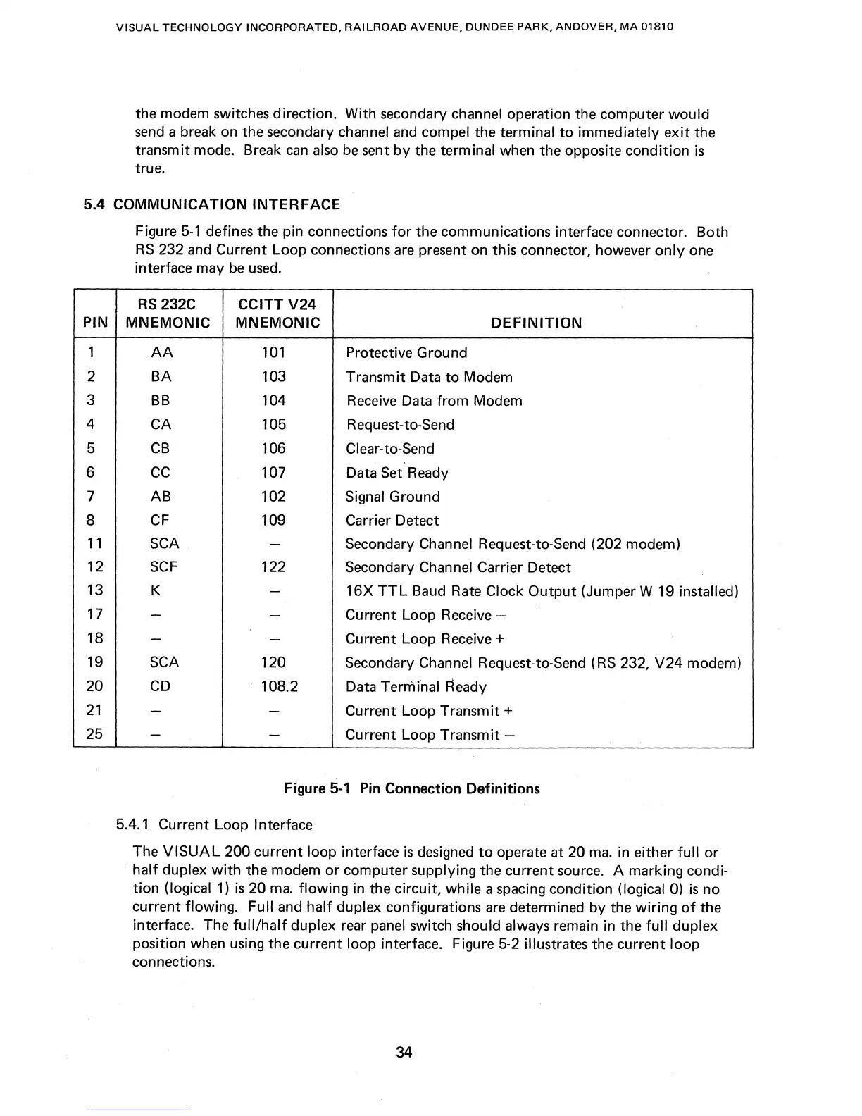
Figure
5-1
defines the pin connections
for
the communications interface connector. Both
RS
232 and Current Loop connections are present on this connector, however
only
one
interface may
be
used.
RS
232C CCITT
V24
MNEMONIC MNEMONIC
DEFINITION
AA
101
Protective Ground
BA
103 Transmit Data
to
Modem
BB
104
Receive Data
from
Modem
CA
105
Request-to-Send
CB
106 Clear-to-Send
CC
107 Data Set Ready
AB
102 Signal Ground
CF
109 Carrier Detect
SCA
-
Secondary Channel Request-to-Send (202 modem)
SCF
122
Secondary Channel Carrier Detect
K
-
16X
TTL
Baud Rate Clock
Output
(Jumper W 19 installed)
-
-
Current Loop
Receive-
-
-
Current Loop Receive +
SCA 120
Secondary Channel Request-to-Send (RS 232,
V24
modem)
CD
108.2 Data Termi'nal Ready
-
-
Current Loop Transmit +
-
-
Current Loop Transmit -
Figure
5-1
Pin Connection Definitions
5.4.1 Current Loop
Interface
The
VISUAL
200 current loop interface
is
designed
to
operate at 20
mao
in either
full
or
.
half
duplex
with
the modem
or
computer supplying the current source. A marking condi-
tion
(logical
1)
is
20
mao
flowing
in the circuit, while a spacing condition (logical 0)
is
no
current flowing.
Full and
half
duplex configurations
are
determined by the wiring
of
the
interface. The
full/half
duplex rear panel switch should always remain in the
full
duplex
position when using the current loop interface. Figure 5-2 illustrates the current
loop
connections.
34