Vitrek V4 – Electrical Safety Tester USER MANUAL
60
100MΩ 1000V
M M
±5MΩ
1000MΩ 1000V
M M
±100MΩ
100mΩ 3A
m m
±4.2mΩ
100mΩ 10A
m m
±4.2mΩ
100mΩ 25A
m m
±4.2mΩ
Standards Used Serial No. Cal Date Cal Due
Valhalla 4600 HV DMM 24-1524 09/18/01 09/18/02
Vitrek 501 A Resistance Std 012866 04/02/01 04/02/02
The following portion of this procedure is for adjustment of the actual calibration values.
The Vitrek V4 ESTs can be divided into several modules for calibration & adjustment. The modules consist
of: main board, isolation board, AC withstanding voltage, DC withstanding voltage, IR, and Ground Bond.
Calibration Modules
Calibration procedures are built in the software of the EST series. Please follow as:
1. Connect with high voltage transformer & main board. The safety cover should be closed.
2. Press UTILITY key and press power SW. While the machine is turned on, keep pressing the UTILITY key
until the LCD shows “PRESS START TO PROCESS”.
3. While the machine is warmed up, the LCD monitor will display the model name.
4. Check the model name. If it’s not the same model name, turn off the power and repeat the “MODEL
SETTING”.
5. In the meantime, EST series will self test the grounding condition of power line. If the earth check failed,
EST series will be alarmed. Therefore, turn off the power and re-check grounding again.
6. If self-test is passed, the LCD monitor will display the “PRESS START TO PROCESS” message. Press
START key to begin calibration procedures.
7. Select the calibration modules by pressing the left & right arrow key. Press START key to begin calibration
procedures. The calibration procedures are following:
STEP1: AC withstanding voltage- voltage adjustment procedure (STEP1:ACV)
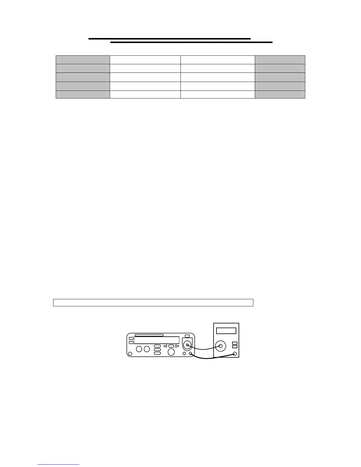
1. Connect V4 unit to Vitrek 4600A high voltage meter.
2. Follow “Modules Calibration Starting Procedures”, Select the calibration module “STEP1:ACV” by
pressing START. Use the left & right arrow key to select 50 or 60Hz. Press START key to begin
calibration procedures.
3. 600V will be calibrated first. Use knob and left & right arrow key to adjust the value of the LCD monitor.
The readout of high voltage meter shall be monitored in the same time. If the meter’s readout reaches
600V (±2V), wait for 3 seconds and press EDIT/SAVE key.