VIVOTEK
8 - User's Manual
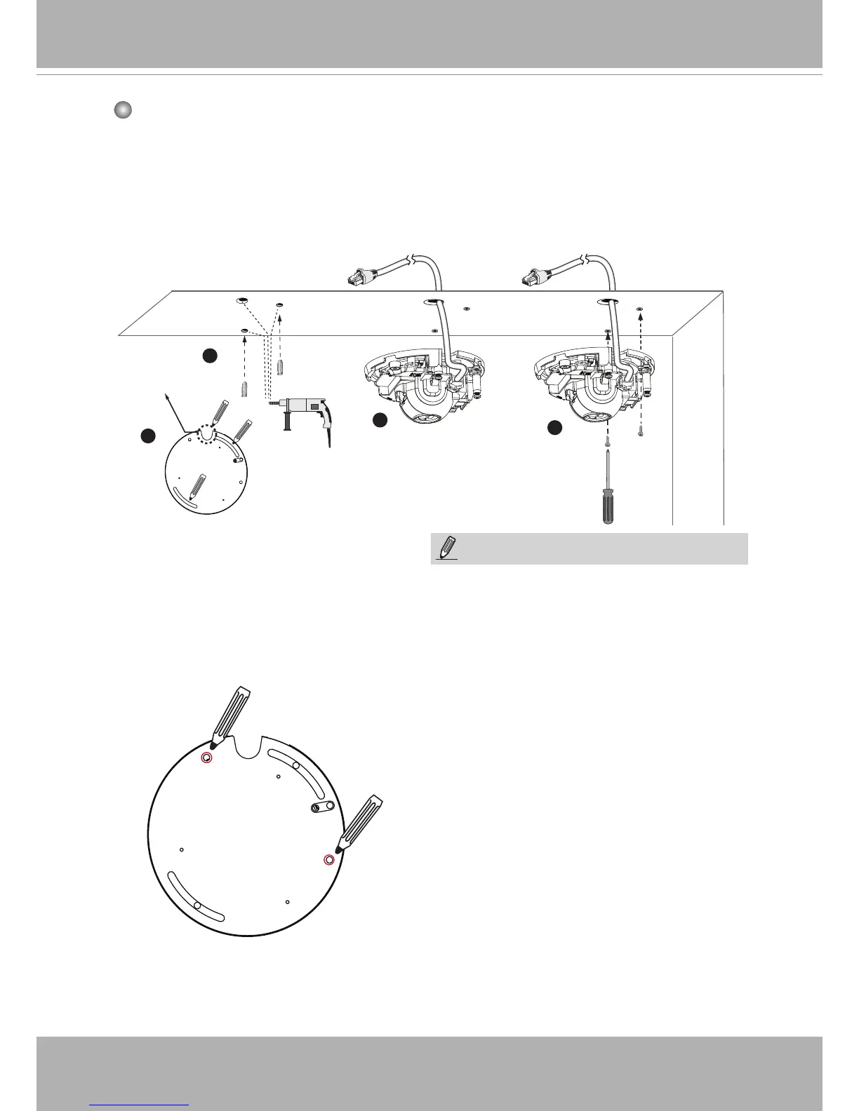
Mounting the Network Camera - Ceiling or Wall Mount
2
3
1
4
NOTE:
1� Do not completely tighten the mounting
screws in the screw slots yet� You may
need to turn the camera left or right for a
best shooting direction later�
2� The camera can only be powered by PoE�
There is no DC or AC input connector�
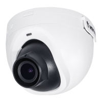
Routing hole
position
5� After tuning the camera's shooting
direction and tilt angle, you can remove
the camera and drill another 2 holes to
the ceiling for better support� For vandal-
proof applications, you can secure the
camera using all 4 mounting holes�
1� Use the alignment sticker as a template to mark where holes will be drilled on the
ceiling� Drill two holes into the ceiling; and hammer in the plastic anchors�
2� Drill another hole if you want to route cables through the ceiling or wall�
3� Connect and route an Ethernet cable through the ceililng or wall�
4� Temporarily attach the Network Camera to the ceiling using two included screws�