2.4 Completing the installation
1. Check all lines to ensure that they are properly routed, secured and that all fittings are
tightened.
2. Check all cap screws mounting the bracket and components to the engine to ensure
that they are properly torqued.
3. Check all belts to ensure that they are installed properly and that the pulleys, idlers
and tensioners are correctly aligned.
4. Check all hoses and hose clamps to ensure that they are connected correctly and that
the hose clamps have been tightened.
5. Check the coolant level in the engine to make sure that it is correct. Remember to run the
engine to operating temperature and check the coolant level to make sure that it has not
changed.
6. Check the oil filter to make sure that it is properly tightened. Failure to tighen the filter
properly will result in it blowing off the filter mount.
32
DOCUMENT 19297
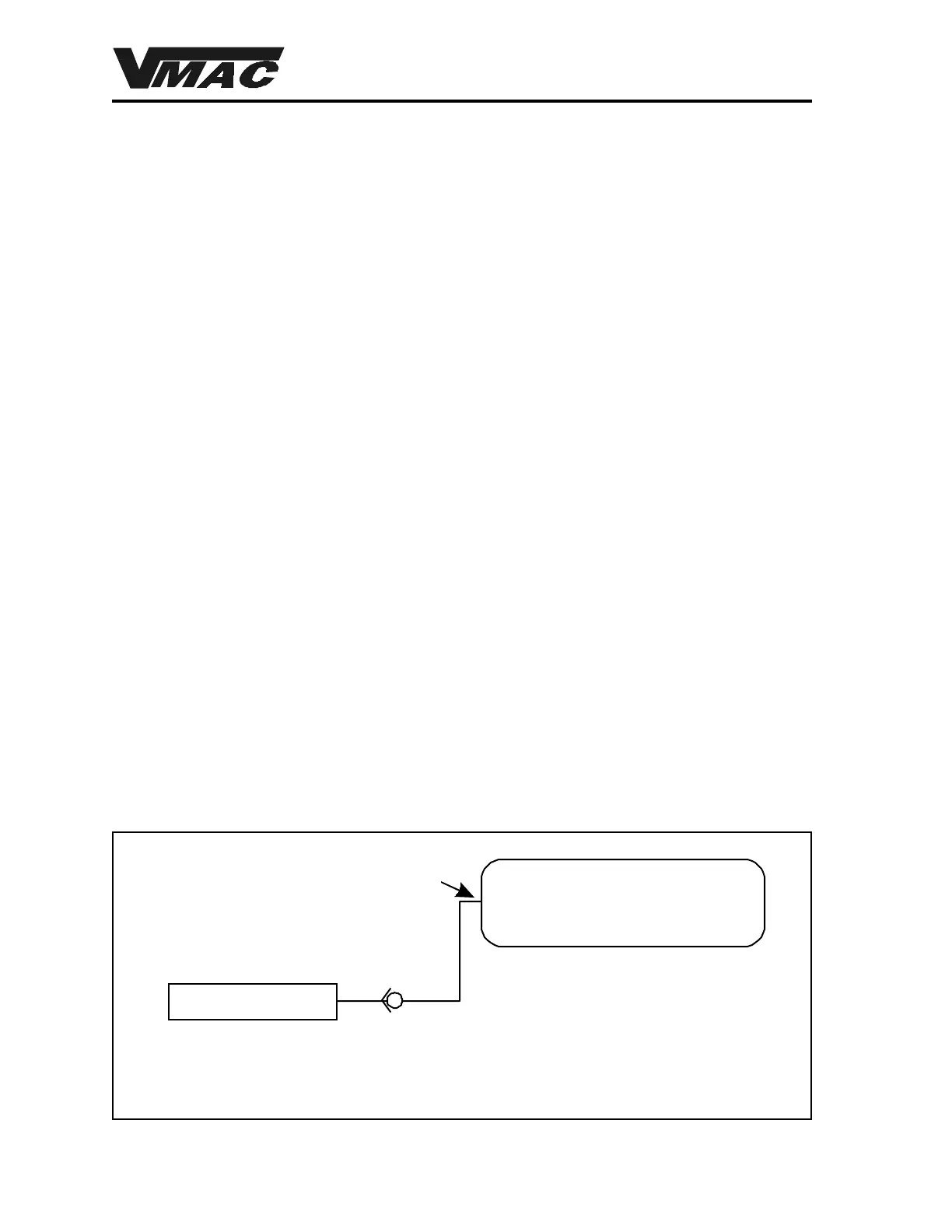
Special installation notes
If you intend to use an auxiliary air receiver with this system you must observe the following
installation procedure (Figure 26a) . Failure to observe this procedure will result in damage to the
system. Also note that this type of installation will result in a delay in the actuation of the mechanical
throttle by approximately 30 seconds.
1. The line from the VR7000 tank to the auxiliary air receiver must have a one-way check
valve installed to prevent blowback from the auxiliary tank and to prevent moisture from
entering the VR7000 tank.
2. The line to the auxiliary tank must not be installed in the bottom of the tank, but must be
installed as high as possible to prevent water from clogging the line.
VR7000 Tank
Auxiliary Receiver
One-way check valve
Install the line as high as
possible, NOT on the
bottom of the tank
Figure 26a