42
4.2 Connecting the wiring harnesses
1. Make sure that the underhood harness cannot become pinched or damaged. Fasten the
harness out of the way with nylon ties if necessary.
2. Using a test light, locate a fuse in the fuse panel that will provide power only when the
ignition switch is in the “ON” position.
3. Insert the supplied electrical connector into the back of the fuse panel and connect the wire
with the inline fuse holder to the connector.
4. Connect the green wire to a good ground.
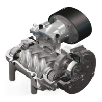
5. Route the white wire along the firewall and along the right-side valve cover to the VR7000
compressor. Connect this wire to the compressor clutch connection.
6. Connect the 18 gauge red wire to the throttle controller.
7. Connect the temperature sensor wire from the electronic control unit to the matching
connector from the compressor.
8. Remove the OEM connector from the park brake switch.
On manual transmission models
9. Connect the black wire from the interface connector to the connector on the park brake
switch.
10. Connect the OEM connector and the black wire from the control unit to the piggyback
connnector.
11. Connect the OEM wire to the piggyback connector at the park brake switch.
On automatic transmission models
12. Connect the black wire from the interface connector to the black wire with the matching
connector on the Drive Disable Circuit.
13. Install the Drive Disable Circuit under the dash using nylon ties.
DOCUMENT 19299
7. Connect the two interface connectors together. Route the white wire, 18 gauge red wire
(without the fuse holder) and the wire for the compressor temperature sensor from the
electronic control unit through a suitable opening in the firewall. If necessary, you can cut a
small slit in the rubber sealing boot where the steering column passes through the firewall.