43
DOCUMENT 19299
14. Connect the black wire from the Drive Disable Circuit with the piggyback connector to the
connector on the park brake switch.
15. Connect the OEM wire to the piggyback connector at the park brake switch.
16. Route the blue wire into the engine compartment along the same route as the other wires.
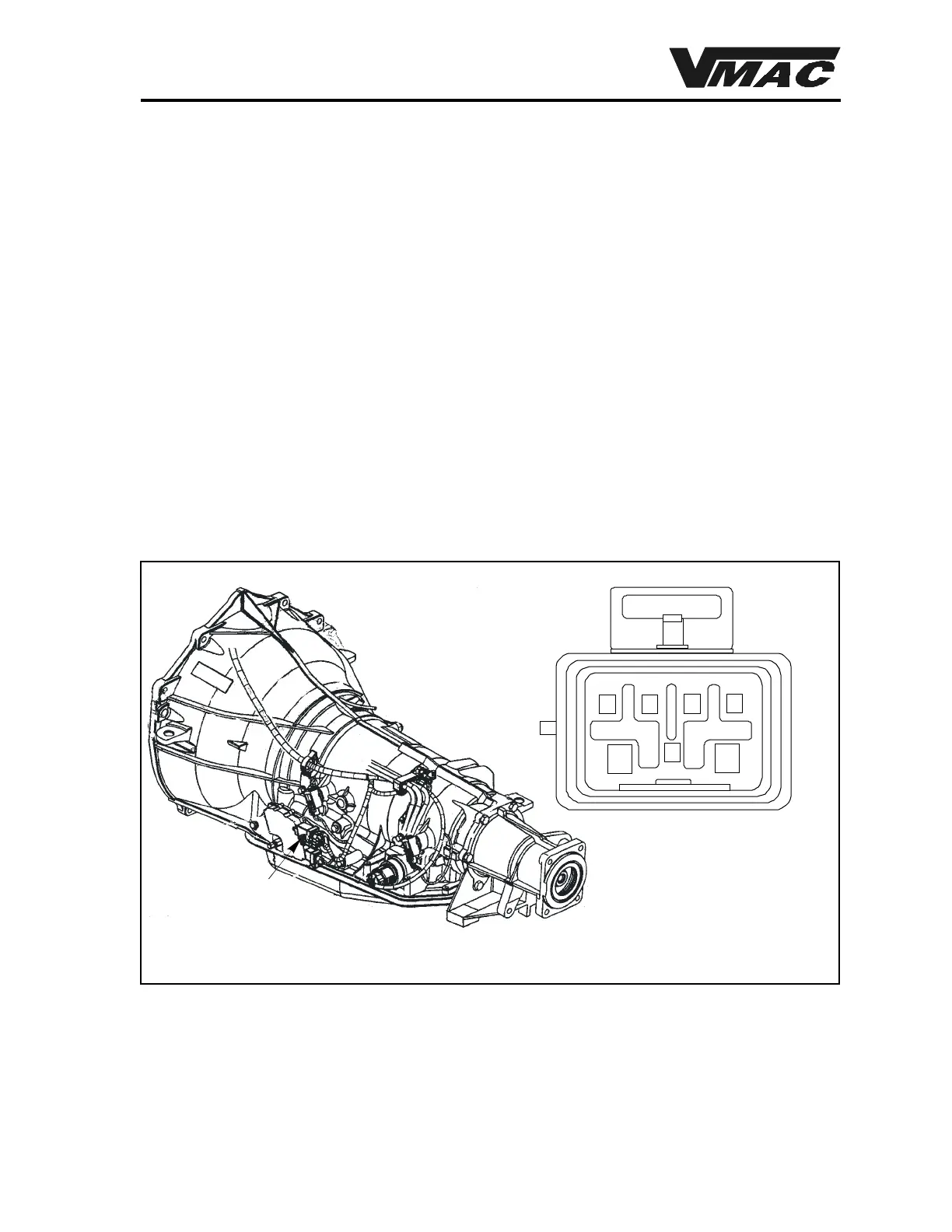
17. Locatethe light green wire at cavity B in the 7 pin connector at the transmission (Figure 4.2).
18. Either install the supplied blue female quick-connector at this locationor trace the wire to a
suitable “out-of-the-weather” location under the hood. If you trace the wire, make sure that
there is battery voltage present with the transmission gear selector in park and the ignition in
the “ON” position.
19. Plug the blue wire from the Drive Disable Circuit into the quick-connector, then tape the
connection securely to prevent corrosion.
20. Check the routing and security of all wiring. Fasten all wiring into position using nylon ties
so that they do not contact moving parts or hot areas.
7-pin connector
AB
C
D
E
F
G
Figure 4.3 Transmission connector location