27
DOCUMENT 19297
2.2 Connecting the air and oil lines
1. This procedure will follow the installation of each individual line, show the location on each
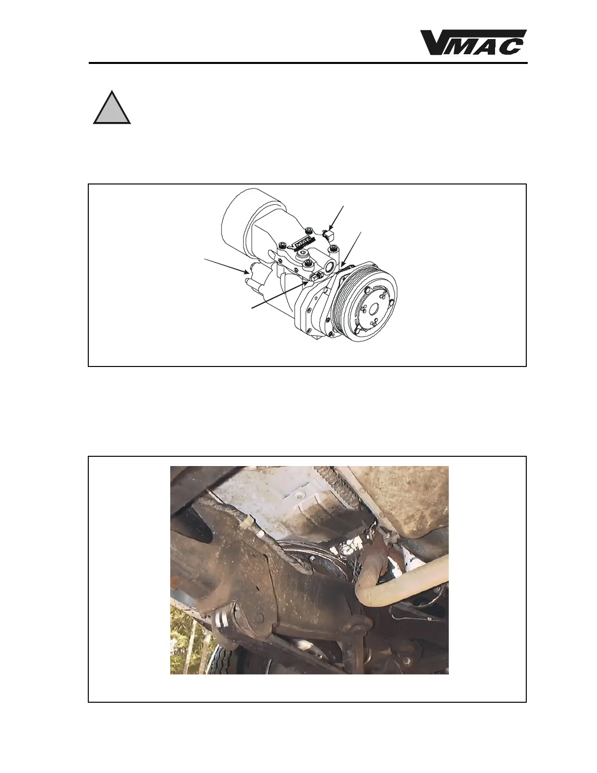
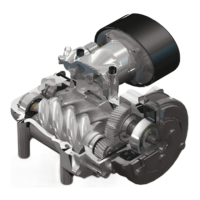
component and describe the complete process. Figure 18 shows the location of lines at the
compressor.
The lines must be installed in the correct locations or the system will not function
properly. In addition, a hazardous situation may develop from oil spray, potential
fire or explosion.
Figure 18
Oil Return Line From
Remote Filter
Scavenge Line
Main Line
1/4” Red Polytube
From Throttle Controller
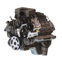
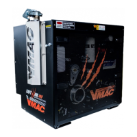
Figure 19
WARNING
!
2. Route all lines so that they are clear of moving parts. Secure all lines using the appropriate
tie-wrap or chassis clip to keep them in place. Do not allow lines to contact hot engine
components or exhaust components. Stainless steel tie clips are provided for hot oil hoses
or for extra strength securing. Cut short lengths of plastic covering, apply to lines and tie in
locations where the hoses contact each other or the truck. Abrasion can wear through the
surface of the hose. Figure 19 shows the tank lines routed over the frame.