Vogels Autogas Systems VGI Hardware Manual System Description and Installation
VGI Technical Manual 2014-01-14.pdf Pagina 6 van 44
1.2.2 Outlet signals
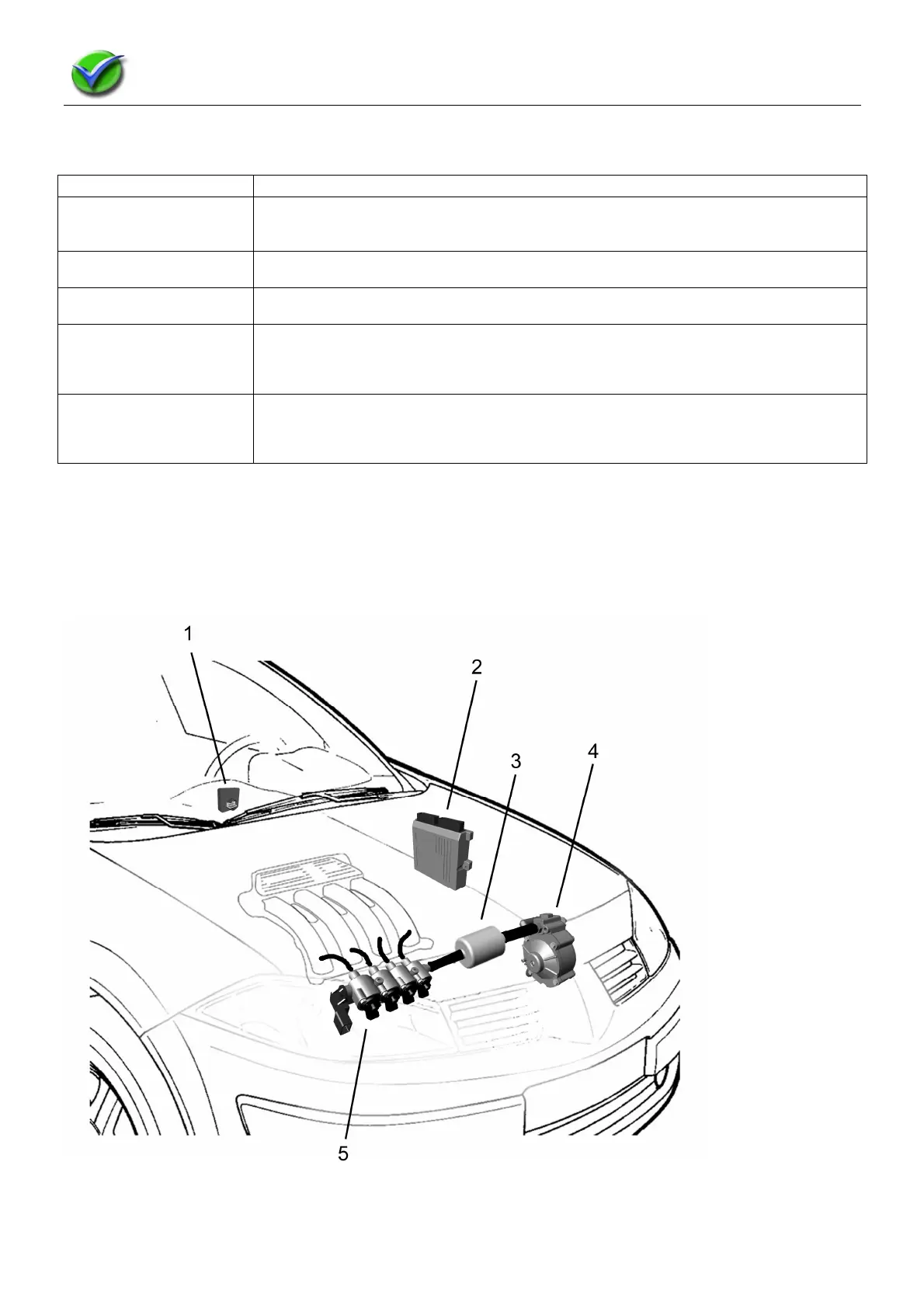
1.3 Components survey
1 Fuel switch / User interface
2 Gas ECU (Electronic Control Unit)
3 Dry gas filter
4 Pressure regulator
5 Gas injector rail with pressure and temperature sensor
Image is copyright protected by Luccio Engineering
Outlet signal Function
Gas-injectionsignal The main outlet signals are gas injector signals which determine the amount of
injected fuel into the engine. Each cylinder has its own injector and signal. Petrol
injection signal of cylinder A corresponds with gas injector A.
Tank solenoid signal This signal opens or closes the solenoid valve on the outlet of the LPG tank, so LPG
can or cannot run to the pressure regulator.
Gas solenoid valve This signal opens or closes the solenoid valve on the inlet of pressure regulator, so
LPG can or cannot run into the pressure regulator and the rest of the system.
Serial communication
with the fuel switch.
The fuel switch and Gas ECU are connected with each other through a serial
communication link. They inform each other on fule selection, fuel level and possible
diagnostics errors.
Serial communication
with a PC.
Using an interface cable and an interface program on the PC or laptop it is possible to
check the system and modify settings. The gas ECU and PC communicate trough a
serial connection.