Vogels Autogas Systems VGI Hardware Manual System Description and Installation
VGI Technical Manual 2014-01-14.pdf Pagina 8 van 44
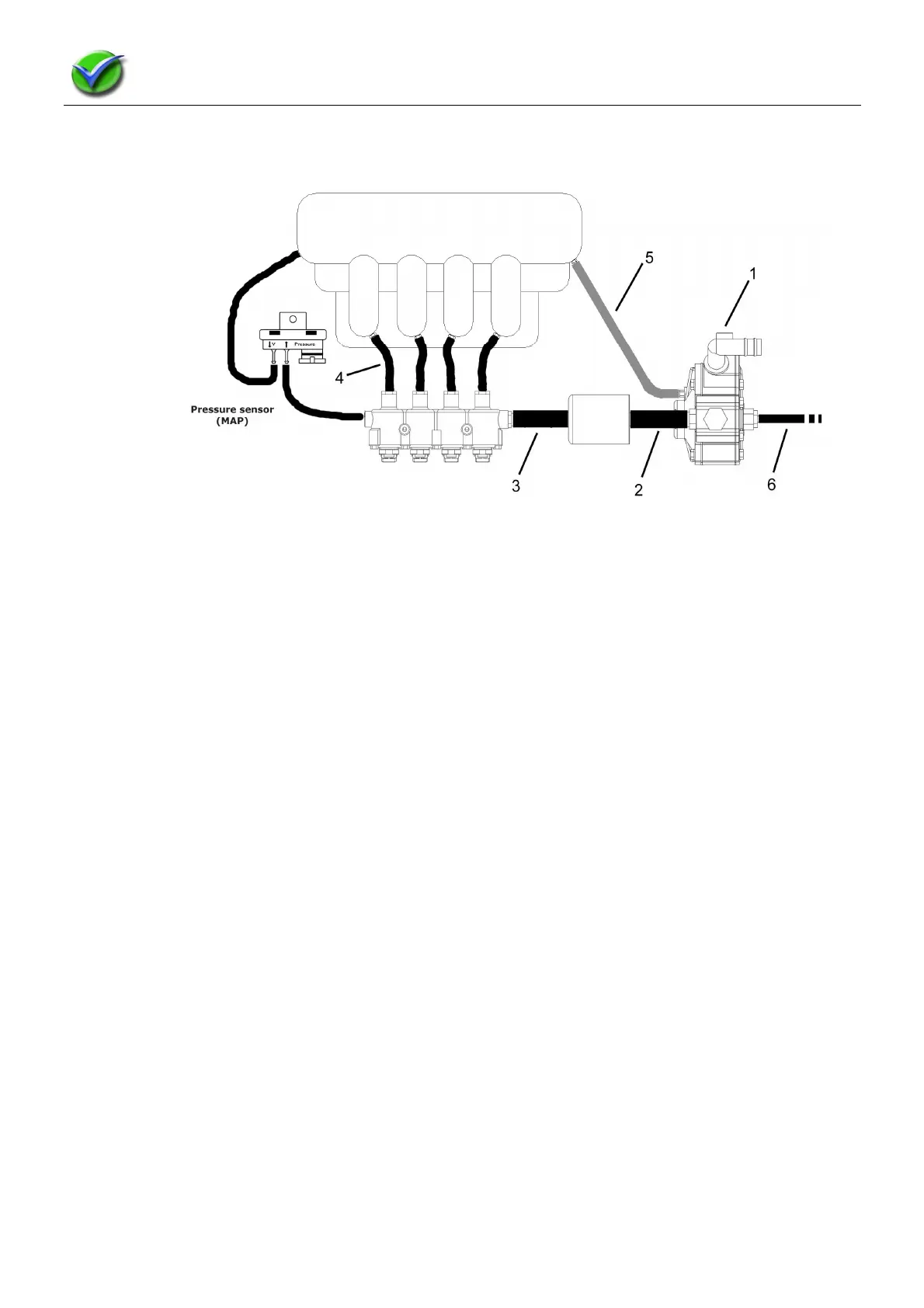
1.5 Gas hoses survey:
The pictures below give a schematic view of how the (gas) hoses are connected to the various gas components
and therefor how these components are connected to one another.
Images are copyright protected by Luccio Engineering
Legenda:
1. LPG-inlet
2. 14 mm hose between pressure regulator and gasfilter.
3. 14 mm hose between gasfilter and injectorrail.
4. 6 mm hose between injectorrail and nozzle in inlet manifold.
5. MAP-connection
6. Overpressure connection. The hose has to finish outside of the enige compartment (R-67-01)
Gas hose installation instructions:
• Avoid gas hoses to run closely to heat sources.
• Avoid gas hoses to run past sharp objects and possibly be damaged in time.
• Connect the gas hoses correctly to the components and avoid and check for leakages.