26
Manual engagement of reverse gear (safety system)
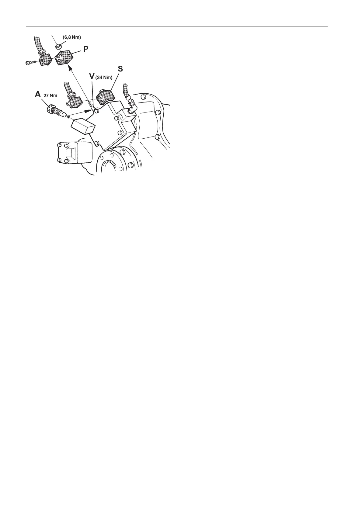
A. Plug*
P. Solenoid – “Primary”. Used for Forward movement
S. Solenoid valve – “Secondary”. Used for Astern movement
V. Valve body
*Tightening torque: Max. 27 Nm (2.7 kpm = 19.9 ft.lb.)
Safety systems (TAMD72P)
Reverse gear emergency operation
On Twin Disc reverse gears with electronically oper-
ated shifting there is a safety feature for manual en-
gagement of Ahead (forward movement) should a
malfunction occur on the reverse gear solenoid.
Engagement:
1. Stop engine and remove the key from the key
switch.
2. Note how the cables are attached to the reverse
gear’s solenoids “P”/“S” (Primary/Secondary).
Detach the connectors from both solenoids.
3. Remove the solenoid (1) and the valve body (3)
for forward (Ahead) from the reverse gear (nor-
mally* the valve where the “Primary” cable is in-
stalled).
4. Install the plug** (A) in the hole for the valve body
as shown in the illustration.
Tightening torque: Max. 27 Nm (2.7 kpm = 19.9
ft.lb.)
NOTE! After engagement the reverse gear is
locked for use Ahead and cannot be disengaged.
* Note! For twin engines (counter-rotating propellers) the ca-
ble marked “Secondary” is connected to the solenoid for
Forward (Ahead) movement (marked “Primary”) on the port
engine (propeller rotates to the left).
** The plug is supplied with the reverse gear.
Separate power supply
If the battery voltage should for some reason drop to
a level that is too low when the engine is running (no
charge from the generator and batteries discharged),
the engine will stop.
In order to start the engine a back-up power system
is required. One possible solution for installing a
back-up reserve is given in the engine’s standard
wiring diagram on page 79 (12V) and page 81 (24V
system).
To switch to the back-up system use the main switch
(2
B
in the wiring diagrams) which switches the emer-
gency/accessories batteries into circuit with the start-
er batteries.
NOTE! The back-up system batteries must be
charged, for example by the engine’s generator (not
shown on the engine wiring diagrams).
Note! This system is not factory installed from Volvo
Penta, it must be installed and connected during the
engine installation.
Check the Instruction Book for the boat to see if
there is an alternative reserve power supply de-
scribed there.
NOTE! A short-circuit in the electrical system will re-
sult in the semi-automatic fuses being triggered and
the engine will stop.* Before starting the engine diag-
nose and correct the malfunction that caused the
short-circuit.
*Note: See page 66 for resetting fuses.