69
3
4
8
7
7
12
9
77
6
5
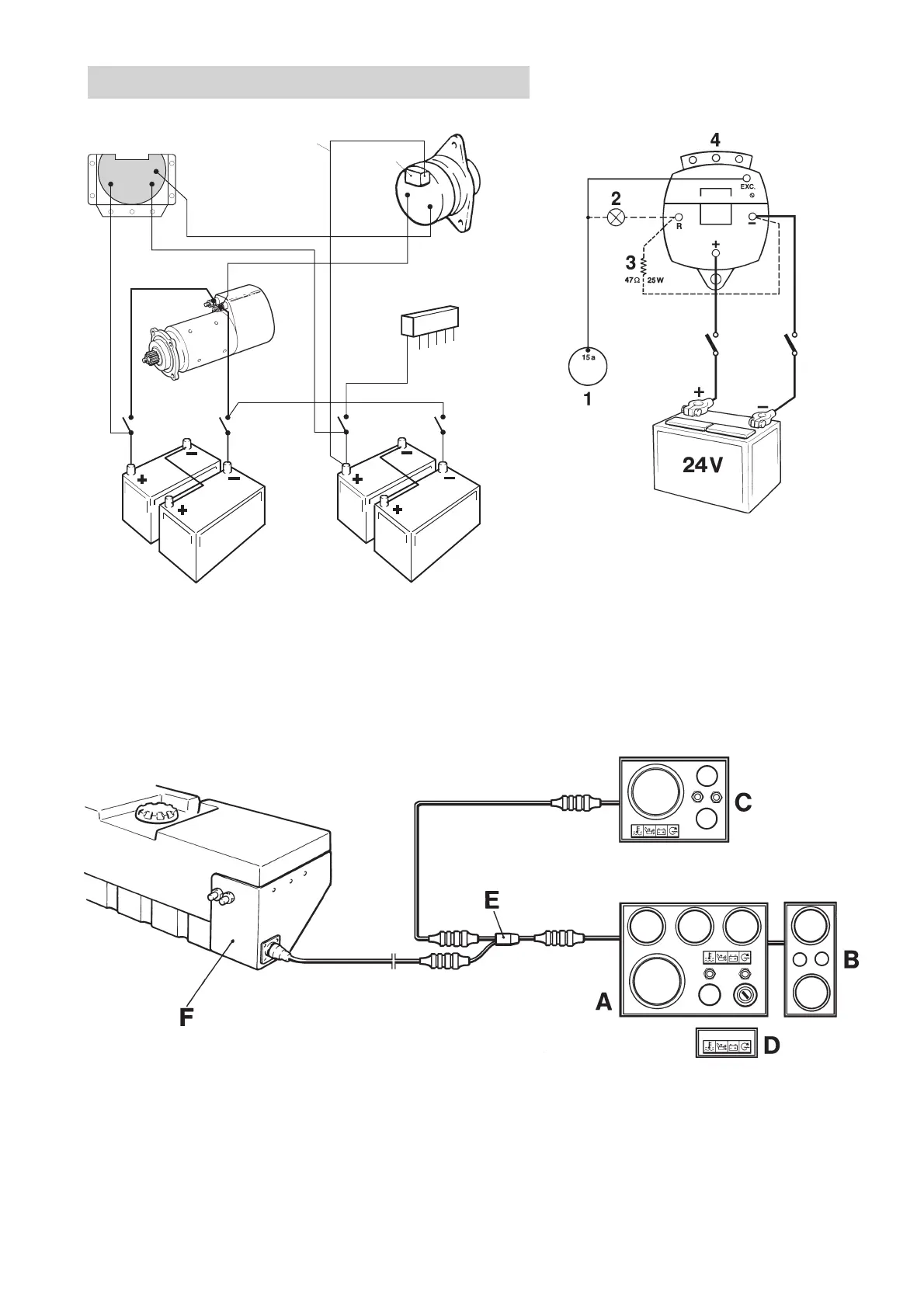
Wiring Diagrams
Connection of sensor system to standard generator, basic
diagram
1. Sensor cable (yellow, 1.5 mm
2
) 6. Starter motor
2. Charge distributor (accessory) 7. Main switch
3. Voltage regulator 8 Accessory batteries (for
4. Generator accessories)
5. Fuse panel (accessory) 9. Start batteries (engine)
Block diagram
A. Main panel D. Alarm panel (Used only when there is no main
B. Supplementary panel “A” panel)
C. Flying Bridge panel* E. Y connector
F. Junction box** with fuses
*Main panel (“A”) may also be fitted in the ** Note: The picture shows the TAMD71 and
Flying Bridge. Senders for temperature and oil TAMD72WJ.
pressure must then be replaced.
Connecting the charge indicator lamp
Extra generator 28V/100A
1. Key switch
2. Charge control lamp
3. Resistor (47Ω/25W),
P/N 863400-8
4. Generator 28V/100A