68
Stop solenoid
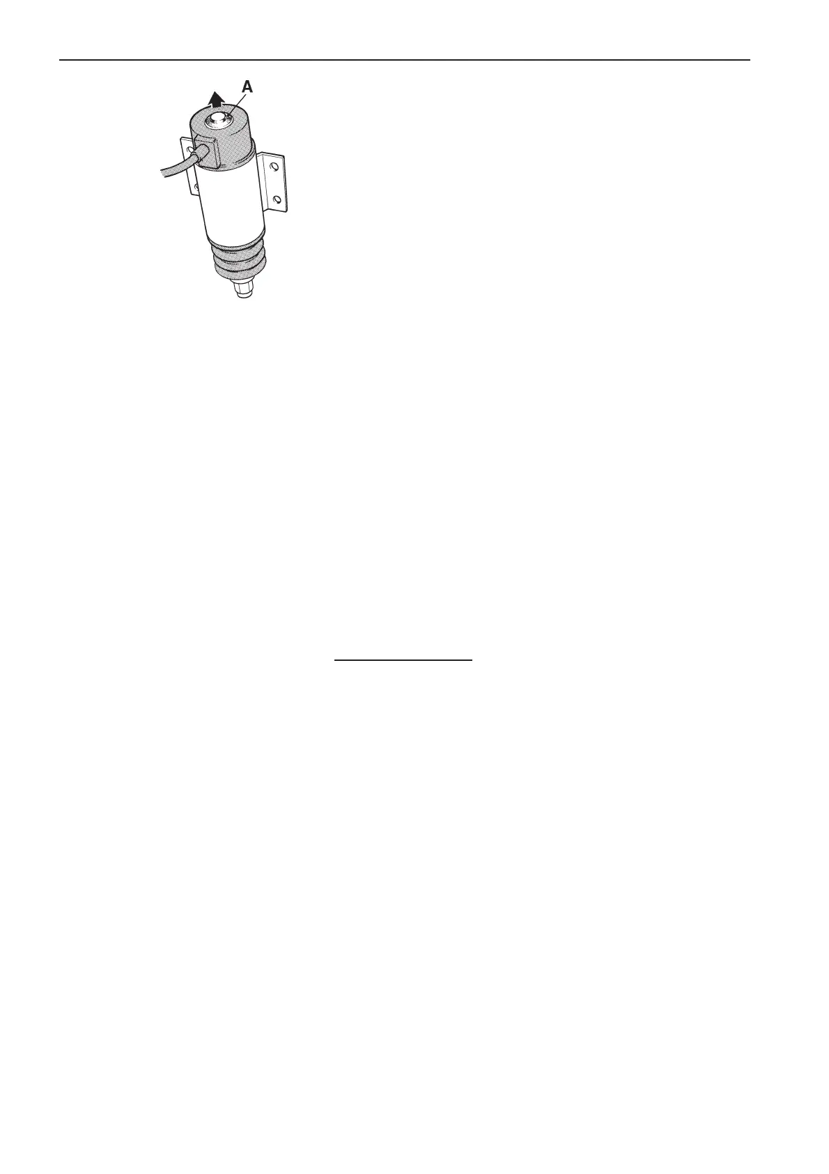
A. Stop position indication
Stop solenoid
Setting the stop solenoid should be left to author-
ized service personnel. Incorrect setting may
lead to the solenoid burning out.
However, a rough check may be carried out as fol-
lows:
1. Check that the stop solenoid and its operating le-
ver are properly tight.
2. Get someone to assist by engaging the stop so-
lenoid by turning the starter key to position “S”.
Alternatively, the solenoid may be engaged di-
rectly via the connector at the solenoid. Disman-
tle the connector and connect pin 4 to negative
(–). Connect a check lamp between pins 3 and 4.
Then switch on the power to pin 1 (+) via a fuse
(16A for 12V, or 8A for 24V system voltage). The
solenoid will be engaged and the control lamp
will come on (shows that the solenoid has en-
gaged the hold winding).
3. Check that the stop solenoid is engaged without
seizing and that the stop position indicator on the
top of the solenoid (TAMD71), (rear in the
TAMD72) is pushing out the rubber diaphragm
(see illustration). This shows that the stop sole-
noid is in the bottom position.
4. Check that there is clearance of 1–2 mm (0.040–
0.080") between the stop lever and the injection
pump’s end stop.