47
Technical description
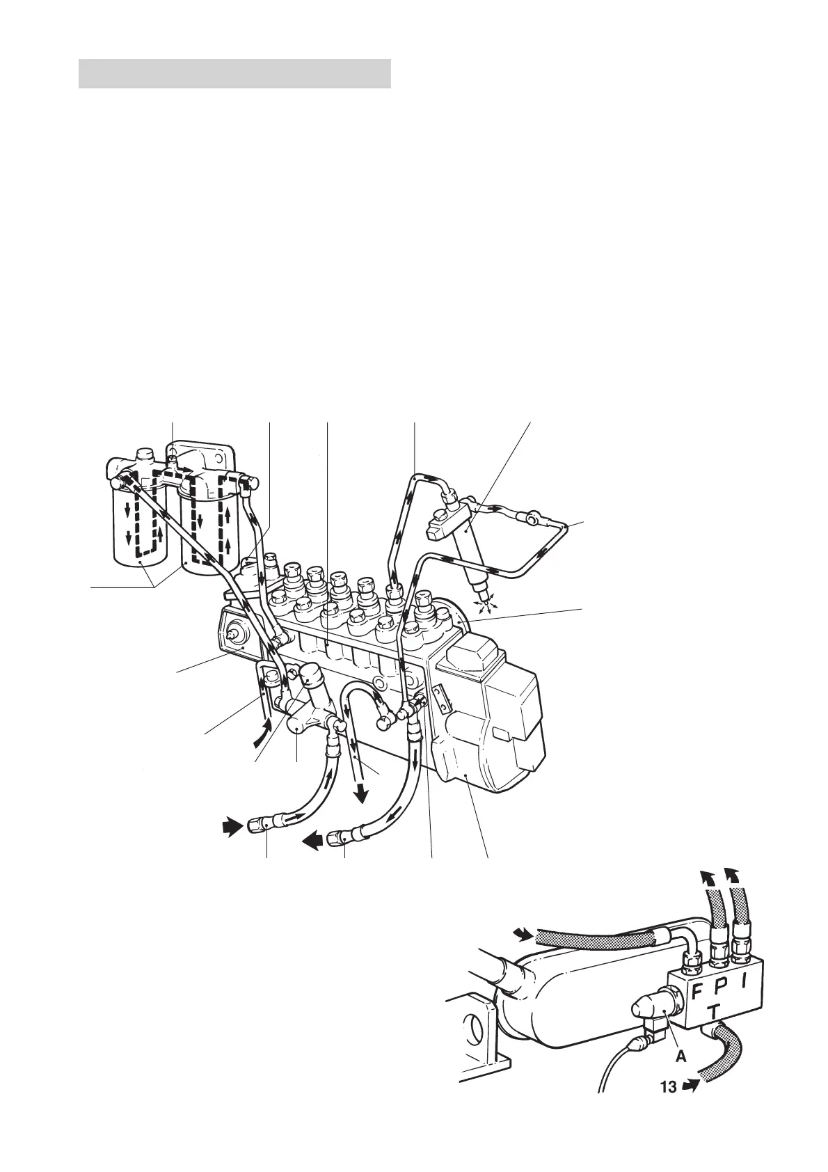
Fuel system
The fuel is drawn up by the feed pump from the fuel tank through the pre-filter(s) and is forced through the fine
filters to the injection pump. Excess fuel escapes via the overflow valve back to the tank. This valve is located
on the injection pump. This means that the return fuel flushes through (cools) the injection pump’s fuel cham-
ber. This evens out fuel temperature so it is is the same for all the cylinders and prevents gas bubbles forming
in the fuel line.
The injection pump then forces the fuel under high pressure to the injectors, which atomize the fuel when it is
sprayed into the engine’s combustion chambers.
Return fuel from the injectors returns to the tank via the overflow valve.
Fuel system
1. Fine fuel filters
2. Venting screw
3. Pressure line from intake
manifold (charging pres-
sure)
4. Injection pump
5. Pressure pipe
6. Injector
7. Fuel return pipe
8. Pressure equalizer
9. Centrifugal governor
10. Overflow valve
11. Return pipe, lubricating oil
12. Return line to fuel tank
13. Fuel line, intake
14. Feed pump
15. Hand pump
16. Engine oil line, inlet
17. Smoke limiter
TAMD63, TAMD71*, TAMD72WJ*:
Solenoid valve (fuel cut-off valve) for
stopping engine
*As of and incl. engine No. 207181084/xxxx.
A. Solenoid
Connections in valve housing, markings:
T. Inlet from fuel tank (Tank)
P. Outlet to feed pump (Pump)
F. Inlet from fuel finefilters (Filters)
I. Outlet to injection pump (Injection pump)
2345 6
1
7
8
13 12 10 9
11
15 14
17
16