Auxiliary panel
1. Instrument lighting
2. Oil pressure gauge, reverse
gear
3. Turbo charging pressure gauge
4. Connection to instr. light. on
main panel
5. Connection to printed circuit
card on main panel
6. Connection to connector (18)
on main panel
Conversions mm
2
/AWG*
*American Wiring Gauge
mm
2
1.0 1.5 2,5 10 16
AWG 16 (17) 15 (16) 13 7 5
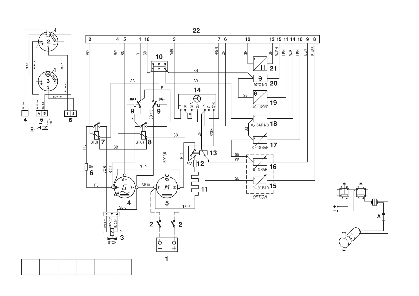
Engine
Note. The components in the wiring diagram
have the same numbers as shown in the key
diagrams on page 61.
1. Battery
2. Main switch
3. Solenoid valve (fuel shut-off valve)
4. Generator (GEN)
5. Starter motor
6. Fuse (8A) for fuel shut-off valve*
7. Stop relay*
8. Starter relay*
9. Semi-automatic fuses (8A)*
10. Ground terminal block*
11. Starter element
12. Fuse (150A) for starter element
13. Relä för startelement
14. Timer relay*
15. Oil pressure sender, reverse gear
16. Pressure sender, turbo pressure
17. Oil pressure sender, engine
18. Oil pressure switch, engine
19. Engine coolant temperature (ECT)
sender
20. Engind coolant temperature (ECT)
switch
21. Engine speed (RPM) sender
22. 16-pin connector*
*Located in the junction box
Suggested connection of oil scavenging
pump (draining and filling)
Cable area 1.5 mm
2
.
A. Fuse (8A/24V, or 15A/12V)
NO = Normally open during operation
The cable run marked with a dashed line is not
supplied by Volvo Penta.
Cable color
BL = Blue R = Red
LBL = Light blue SB = Black
BN = Brown TP = Transparent
LBN = Light brown (colorless)
GN = Green VO = Violet
GR = Gray W = White
OR = Orange Y = Yellow