Group
28
Igni
t
io
n
systems
D
esign
and
funct
ion
-
Compensation
functions
Throttle
switchlidling
(air
control)
switch
Function
and
location
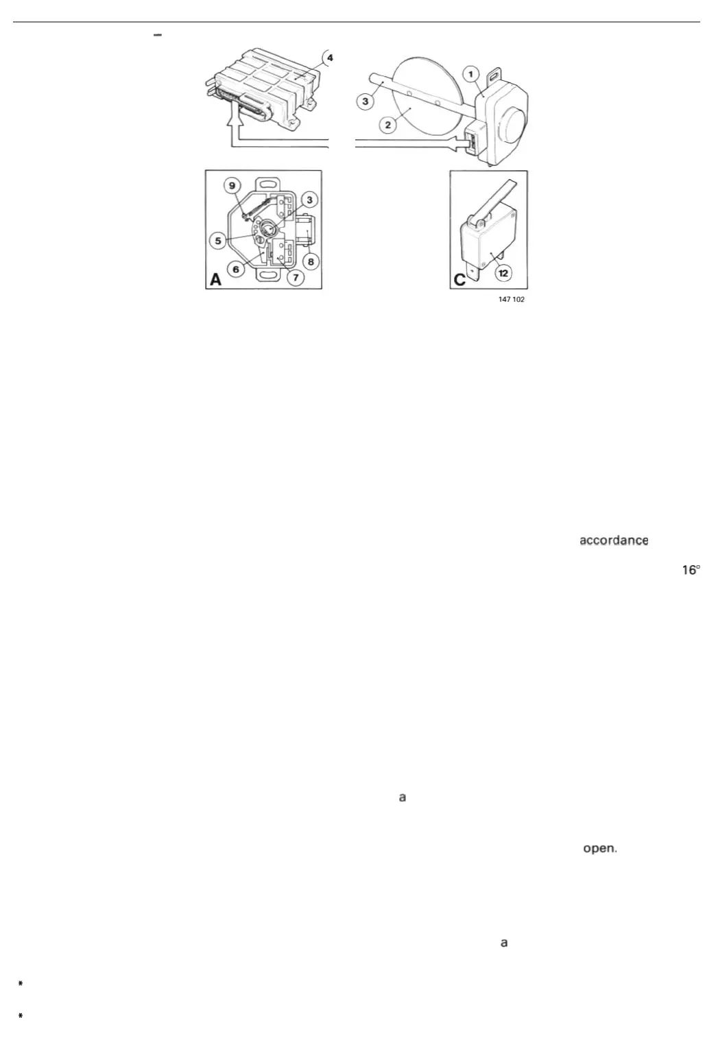
The
throttle
swi
tch (1)
sup
plie
s a signal
to
the
ignition
system c
ontrol
unit
when
the
throttle
is
fully
closed.
The
si
gnal
is used to
enable
th
e
con
trol
unit
(
4)
to
select a t
im
ing
setting
whi
ch is suitable
for
idli
ng
and
engi
ne
braking
con
di-
ti
ons. The
thr
o
tt
le
swi
tch detects
the
throttle
position
(2)
by
measuring
the
rotation
of
the
spindle
(3).
Signal
Thr
o
tt
le
closure
(for
example
under
idling
and
engine
braking
condi
tion
sJ
grounds
one
of
the
sw itch
terminals
, al-
lowing
a cu
rrent
to
flow
from
one
of
th
e
term
i
nals
on
the
con
tr
ol
uni
t.
The
ground
current
is
interpreted
by
t
he
con-
trol
unit
to
determine
,
on
the
basis
of
engine
speed
info
rmat
ion,
whether
the
conditions
are
those
of
idling
or
engine
brak
ing.
Idling
At
speeds close
to
idling
,
the
signal
causes
the
control
un
it
to
adopt
a 'fixed'
igni
t
ion
setting
in
accordanc
e
with
the
idling
program
. Since
the
engine
is
not
required
to
develop
a specific
power
when
idling
, t
he
timing
is
determined
mai
nly
on
the
basis
of
max
i
mum
comfort.
This
means
that
the
se
tt
ing is
well
re
tarded
(
between
approx
. 10"
and
16"
before
ToC
)
to
minimize
the
peak (i.e.
maximum)
pressure
in
the
c
ombustion
chamber
during
the
combus
t
ion
phase,
ensuring
smoo
th, st
eady
running.
Engine
braking
Since
th
e speed is h
igher
under
en
gine
braking
co
nditions,
the
control
unit
timing
cha
ra
cteristic is speed-
dependent
only.
In
general
, the characteristic represents an opt
imum
compromise
between
the
lo
we
st possible
emissions
and
mi
ni
mum
fuel
cons
umpt
ion.
(M
os
t
of
t
he
elect
ronic
fuel
i
njection
syst
ems
used feat
ur
e a fuel
cu
t-o
ff
func
ti
on
which
intervenes
und
er
eng
ine
brak-
ing condi
ti
ons. In this case,
the
fuel
system
control
unit
is also
su
pplied
with
a fUlly-closed
thr
o
ttl
e
signa
l
and
keeps
the
in
jec
t
ors
f
ully
closed
under
these
condi
tions.)
Throttle
switch
type
s
A. Pract
ically
all
fue
l·injec
t
ed
models
in
the
700 series are fi
ned
with
the
type
of
throttle
switch
i
llustrated
.
The
sw it
ch
is
mounted
on
the
thrott
le
spindle
(3J,
which
actuates a
cam
plate (5)
and
an
arm
(6).
The
arm
opera
tes a
microswitch
(7)
which
closes
to
gr
ound
a
terminal
in
the
connec
tor
(8).
(
Apart
from
supplying
a
signal
to
the
control
unit
when
the
throttle
is closed,
the
type
of
switch
used
on
some
en-
gine
variants
i
ncorporates
a
se
t
of
full·load
contacts
(9)
wh
ich close
when
the
t
hrottle
is
fully
open
.
In
th
is case, a
full
-load
signal
is
fed
to
the
fuel
system
control
unit
, ins
tru
ct
ing
it
to
extend
the
injector
opening
period.
However
,
this
feature
is
not
used
on
turb
ocharged
engines.)
C.
The
EZ-118K
sys
tem
employs
an
idling
s
witch
(12)
mounted
on
the
throttle
ca
ble
pulley
to
indicate
w
hen
the
thr
ottle
is
fully
closed
.
The
con
tr
ol
units
use the
signal
to
establish
a
com
fortable
t
iming
setting
when
idling
and
to
activate
th
e
fue
l cut
-off
functi
on
under
engine
braking
con
dit
ions.
The
EZ-118K
control
uni
t
also
uses
the
si
gnal
as a
condi
t
ion
for
advancing
the
tim
ing
for
i
dl
ing
speed
compensa
ti
on
when
a
dr
ive
posit
io
n is
se
lec
ted
on
an
aut
omatic
mode
l
or
th
e
AC
compressor
is
switched
in.
* It
is
ex
tr
emely imponant that t
he
throttleswit
Ch
be
co
r
rec
tly adjusted before
chec
k
ing
the timing, to ensure that the idling setting
is
correctly measured.
*
El
ectronic ignition systems not equipp
ed
with a throttle switch or idling (air control) switch are supplied wi
th
information
on
idling conditions in the form of a
sig
nal
representing the vacuum
in
the intake manifold.
40