Group
28
Ignition
sys
tems
Design
and
function
-
System
descriptions
EZ-116K
EZ-116K
end
Rex-I -
Oiegnostic
system
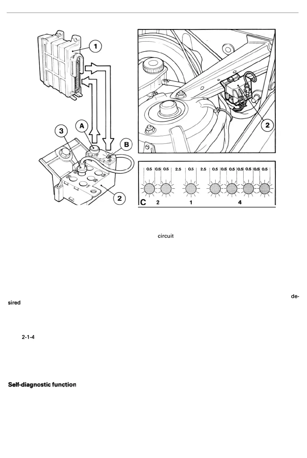
The
EZ
-
116K1R
ex-1control
unit
(
1)
incorporates a
diagnostic
circuit
which
grea
tly
facilitates fault tracing and
monitor-
ing
of
the system. Th e system features
two
separate test functions - a self-diagnostic
function
whereby
the
diag
-
nost
ic
circuit
continuously
mo
nit
ors the operation
of
the
ignition
system, and a funct
io
nal test
program
which
en-
ables
the
operation
of
certain switches to be tested. A
diagn
ostic
unit
(2l,
mounted
beside
the
left
-hand suspension
strut housing in
the
engine
com
partment
, is used to
communicate
with the
diagnostic
circuit
in
the
con
tro
l
unit
.
Oi8gnostic
unit
The
diagnostic
unit
is
provided
with
a coding cable (3),
whi
ch is used
to
select the system (ignition
or
fuel
injection)
to be tested by inserting the
plug
in the a
ppropri
ate socket
under
the
cover
(4).
The sockets are
numbered
fr
om
1
to
7,
the
ignition
system
being
tested using socket
No
. 6. The
pushbutton
(A) on
top
of
the
unit
is used to select
the
de-
sired test
function
.
Oispl8y
codes
A red
LED
(B) is
loc
ated on the
diagno
stic
unit
beside the
pushbutton
. The
LED
displays a series
of
flashing codes
to
indicate
any
faults
wh
ich
may
be present
in
the
system
when
the appropriate test
function
has been act
iv
ated. The
code
2-1-4 is illustrated
in
Fig. C above. As the illustrat
ion
shows,
the
code
consists
of
a
3-digit
number,
ea
ch
digit
of
wh
ich is indicated by flashing
of
the
LED
in rapid succession
(a
t intervals
of
approx. 0.5 seconds). The interval be-
tween each series
of
flashes
which
com
prises an individual
digit
is approx. 2.5 seconds.
NOTE
:
Once
the
self-diagnostic
function
has been selected, a
fault
code w
ill
be
displayed
if
a
system
com
ponent
or
its
wiring
is
faulty
.
On
the
other
hand
,
when
the
functional
test
program
is
selected
,
the
LED
will
display
a
code
confirming
that
the
switch
and
wiring
under
test
are
fault
-free.
Setf.-di8gnostic
function
The self-diagnostic
funct
io
n
monitors
the
same types of fault
as
those stored in
the
con
tr
ol
unit
memory
. (The con-
trol
unit
continuously
monitors
a
number
of the
components
and circuits connected
to
it, detecting
and
stor
ing
any
faults
which
may
occur.) The
memory
accommodates a total of three different faults,
although
the
LED
on
the
diag-
nostic
unit
can
display
up
to seven 3-
digit
fault codes.
NOTE: The memory
will
be erased and
the
fault codes cancalled if the battery is disconnectedl
63