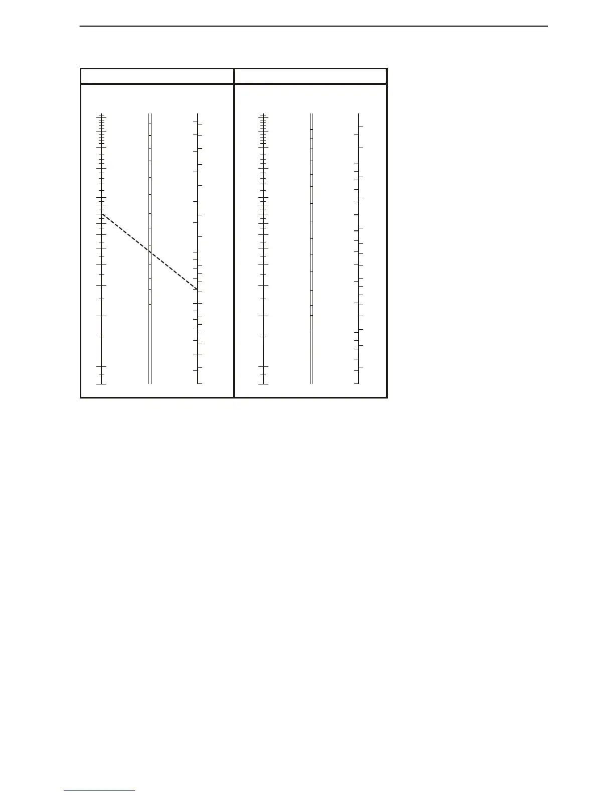
1 Load
A
Length (m)
B Surface (mm²)
C Current (A)
D Output (W)
AWG – American Wire Gauge Example: If a 12 V fridge consumes 70 W and the dis-
tance
between the terminal block and the fridge is four
meters, draw a straight line between 8 (4 x 2) on the
meter scale and 70 on the consumer scale.
The line dissects the area scale in the 2.5 space; 2.5
corresponds to the area required (2.5 mm
2
).
The calculation is based on the maximum permissible
voltage drop in all cables between the positive con-
nection to the consumer and back to the negative
connection.
Total voltage drop when applying the above
table:
12 V system 0.4 V
24 V system 0.6 V
AWG mm² (std) mm² sq. in
18
16
14
12
10
8
6
5
4
3
2
0 (1/0)
00 (2/0)
000 (3/0)
0000 (4/0)
0,75
1,5
2,5
4
6
10
16
16
25
25
35
50
70
95
120
0,82
1,31
2,08
3,31
5,26
8,37
13,29
16,76
21,14
26,65
33,61
53,46
67,40
84,97
107,16
0.0013
0.0020
0.0032
0.0051
0.0082
0.013
0.021
0.026
0.033
0.041
0.052
0.083
0.104
0.132
0.166
Installation, Electrical System
47704162 10-2014 © AB VOLVO PENTA 139