BA E14 track en* 1.3 * E14t_13_510.fm 5-27
Operation 5
Set the maximum oil flow – see chapter “ Adjusting the starting point and
maximum required flow rate” on page 5-31.
Possible damage to the hydraulic hammer.
► Use the jog dial to select one of the hammer symbols B as an
attachment in order to activate the reflux line.
Auxiliary hydraulics – AUX I
The auxiliary hydraulics system is operated with the right control lever.
Adjust the required oil flow.
– see chapter “ Adjusting the starting point and maximum required flow
rate” on page 5-31
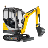
Hammer operation Position
On
Press and hold push button A on the control lever
on the left
OFF Release push button A
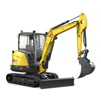
Oil flow Position
To the line on the left Press switch B to the left
To the line on the right Press switch B to the right