11.0 Burners
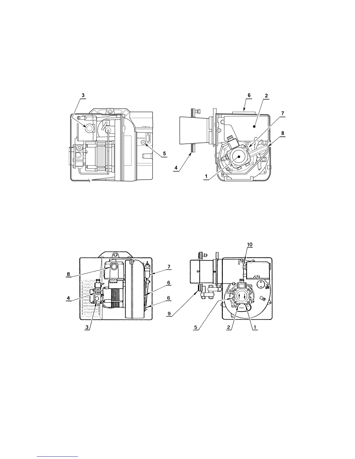
11.1 RDB Burner
The burner is fitted with the correct nozzle and the pressure set. All that is further
required before commissioning, is to connect the oil and electricity supply.
1. Pump 5. Air damper adjustment screw
2. Control box 6. Air tube connection (B/F) or inlet cover
3. Reset button with lock-out lamp 7. Pump pressure adjustment screw
4. Flange with insulating gasket 8. Pressure gauge port
1. Return line 6. Screw fixing air-damper
2. Suction line 7. Hydraulic jack with air-damper
3. Gauge connection 8. Lock-out lamp and reset button
4. Pump pressure regulator 9. Flange with insulating shield
5. Vacuum gauge connection 10. Combustion head adjustment screw
11.2 G10 Burners
Page 35