INSTALLATION
Model
2001
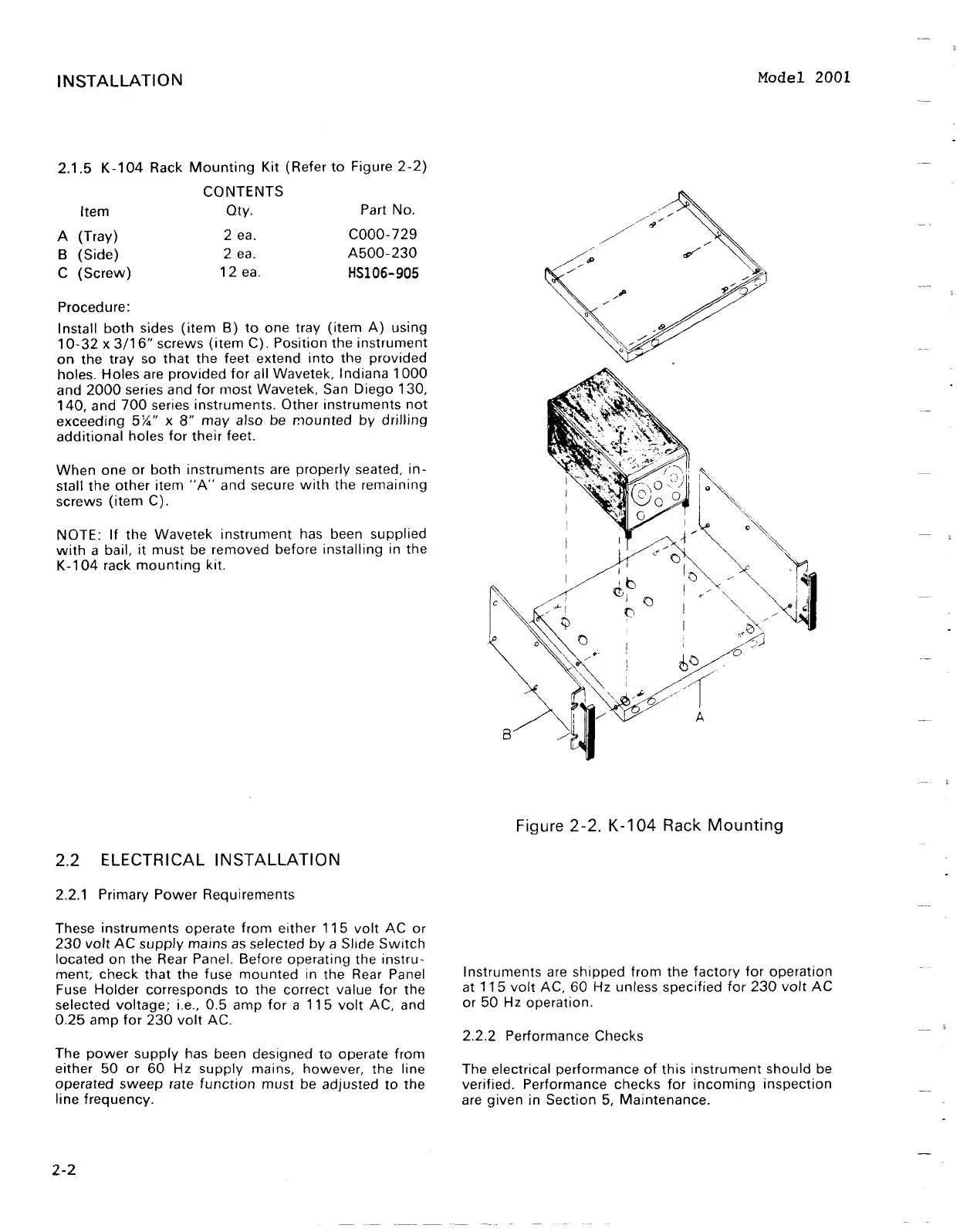
2.1.5 K-104 Rack Mounting Kit (Refer to Figure 2-2)
CONTENTS
Item Qty. Part No.
A
(Tray) 2 ea. COOO-729
B
(Side) 2 ea. A500-230
C
(Screw)
12 ea.
HS106-905
Procedure:
Install both sides (item
B)
to one tray (item A) using
10-32
x
311 6" screws (item C). Position the instrument
on the tray so that the feet extend into the provided
holes. Holes are provided for all Wavetek, Indiana 1000
and 2000 series and for most Wavetek, San
Diego 130,
140, and 700 series instruments. Other instruments not
exceeding
5%''
x
8"
may also be mounted by drjlling
additional holes for their feet.
When one or both instruments are properly seated, in-
stall the other item "A" and secure with the remaining
screws (item C).
NOTE: If the Wavetek instrument has been supplied
with a bail, it must be removed before installing in the
K-104 rack mounting kit.
Figure
2-2.
K-104
Rack
Mounting
2.2
ELECTRICAL INSTALLATION
2.2.1 Primary Power Requirements
These instruments operate from either 11 5 volt AC or
230 volt AC supply mains as selected by a
Sl~de Switch
located on the Rear Panel. Before operating the instru-
ment, check that the fuse mounted in the Rear Panel
Instruments are shipped from the factory for operation
Fuse Holder corresponds to the correct value for the
at 115 volt AC, 60 Hz unless specified for 230 volt AC
selected voltage; i.e., 0.5 amp for a 115 volt AC, and
or 50 Hz operation.
0.25 amp for 230 volt AC.
2.2.2 Performance Checks
The power supply has been designed to operate from
either 50 or 60 Hz supply mains, however, the line The electrical performance of this instrument should be
operated sweep rate function must be adjusted to the verified. Performance checks for incoming inspection
line frequency.
are given in Section
5,
Maintenance.
INSTALLATION
2.1.5
K-104
Rack
Mounting
Kit (Refer
to
Figure
2-2)
CONTENTS
Item
Qty.
Part No.
A
(Tray)
2 ea.
COOO-729
B
(Side)
2 ea.
A500-230
C
(Screw)
12
ea.
HSI06-905
Procedure:
Install
both
sides
(item
B)
to
one tray
(item
A)
using
10-32
x
3/16"
screws
(item
C). Position
the
instrument
on
the
tray so
that
the
feet extend
into
the provided
holes. Holes are
provided
for
all Wavetek, Indiana
1000
and
2000
series
and
for
most
Wavetek, San
Diego
130,
140,
and
700
series instruments. Other instruments
not
exceeding
5X." x
8"
may
also be
mounted
by
drilling
additional
holes
for
their
feet.
When
one
or
both
instruments are properly seated,
in-
stall
the
other
item
"A"
and secure
with
the remaining
screws
(item
C).
NOTE:
If
the
Wavetek
instrument
has been supplied
with
a bail,
it
must
be removed before installing in the
K-104
rack
mounting
kit.
2.2 ELECTRICAL INSTALLATION
2.2.1 Primary
Power
Requirements
These instruments operate
from
either
115
volt
AC
or
230
volt
AC
supply
mains
as
selected
by
a Slide
Switch
located on
the
Rear Panel. Before operating the
instru-
ment.
check
that
the fuse
mounted
in the Rear Panel
Fuse
Holder
corresponds
to
the correct value
for
the
selected
voltage;
i.e., 0.5 amp
for
a
115
volt
AC, and
0.25
amp
for
230
volt
AC.
The
power
supply
has been designed
to
operate from
either
50
or
60
Hz
supply
mains, however, the line
operated
sweep
rate
function
must
be adjusted
to
the
line frequency.
2-2
Model 2001
Figure 2-2. K-104 Rack
Mounting
Instruments are shipped from the
factory
for
operation
at
115
volt
AC,
60
Hz unless specified
for
230
volt
AC
or
50
Hz operation.
2.2.2 Performance Checks
The electrical performance
of
this
instrument
should
be
verified. Performance checks
for
incoming
inspection
are
given
in Section 5,
Maintenance.