MAINTENANCE
Model
2001
detector can be used to recover the signal at levels down to
approximately
-40dBm. Below this level an RF amplifier
or sensitive receiver
(spectrum analyzer) must be used.
Allowability error
is
rt0.5dB to 500 MHz, rtldb to 1000
MHz, and
rt2dB to 1400 MHz. This error is that produced
by the step attenuator alone and does not include the basic
flatness or the vernier attenuator error.
5.3.12
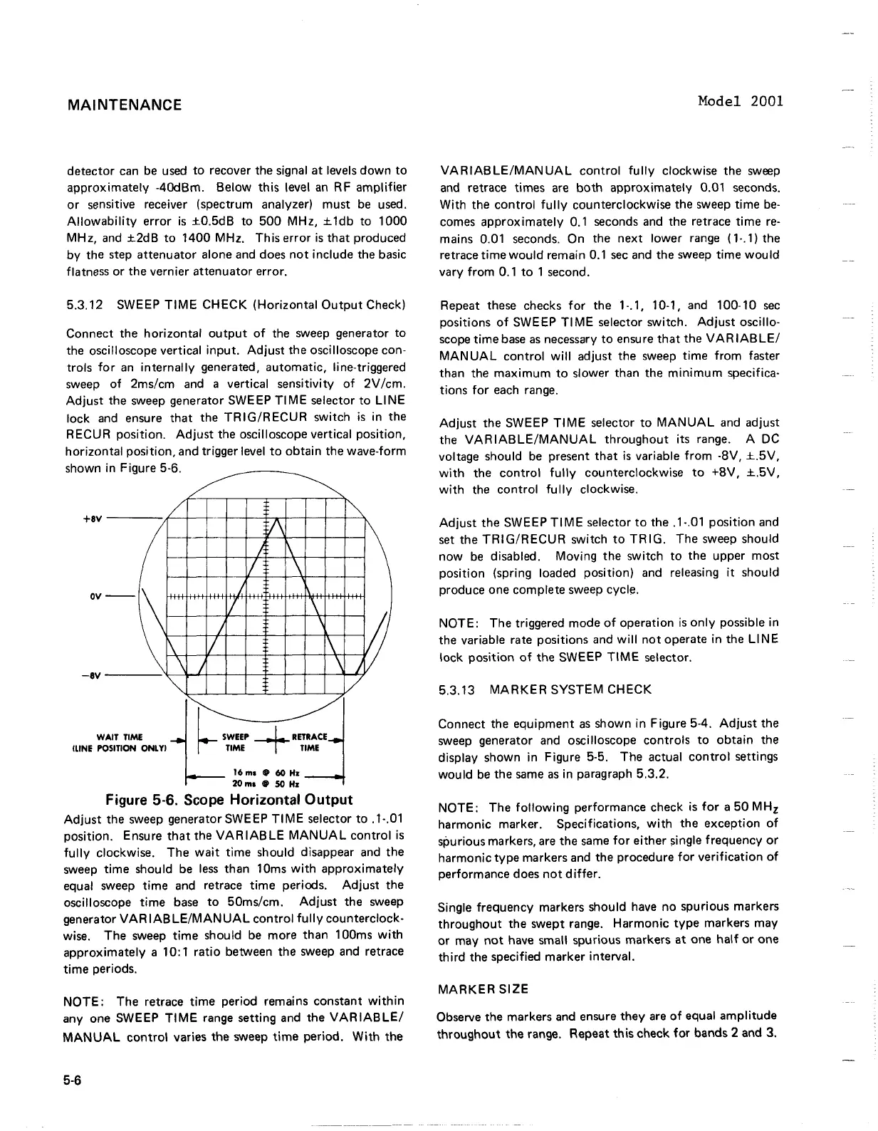
SWEEP TlME CHECK (Horizontal Output Check)
Connect the horizontal output of the sweep generator to
the oscilloscope vertical input. Adjust the oscilloscope con-
trols for an internally generated, automatic, line-triggered
sweep of
2msIcm and a vertical sensitivity of 2VIcm.
Adjust the sweep generator SWEEP TI ME selector to Ll NE
lock and ensure that the
TRIG/RECUR switch
is
in the
RECUR position. Adjust the oscilloscope vertical position,
horizontal position, and trigger level to obtain the wave-form
shown in Figure
5-6.
WAIT TlME
(LINE POSITION ONLY1
16ms
(B
60
HI
20
ms
aB
50
Hx
Figure
5-6.
Scope Horizontal Output
Adjust the sweep generator SWEEP TlME selector to .I-.O1
position. Ensure that the VARIABLE MANUAL control
is
fully clockwise. The wait time should disappear and the
sweep time should be less than
10ms with approximately
equal sweep time and retrace time periods. Adjust the
oscilloscope time base to
50msIcm. Adjust the sweep
generator VAR
IABLEIMANUAL control fully counterclock-
wise. The sweep time should be more than
100ms with
approximately a
10:l ratio between the sweep and retrace
time periods.
NOTE: The retrace time period remains constant within
any one SWEEP TlME range setting and the VARIABLE/
MANUAL control varies the sweep time period. With the
VARIAB LEIMAN UAL control fully clockwise the sweep
and retrace times are both approximately 0.01 seconds.
With the control fully counterclockwise the sweep time be-
comes approximately 0.1 seconds and the retrace time re-
mains 0.01 seconds. On the next lower range (I-.l) the
retrace time would remain 0.1
sec and the sweep time would
vary from 0.1 to 1 second.
Repeat these checks for the 1-.I,
10-1, and 100-10 sec
positions of SWEEP TI ME selector switch. Adjust oscillo-
scope time base as necessary to ensure that the VARIABLE1
MANUAL control will adjust the sweep time from faster
than the maximum to slower than the minimum specifica-
tions for each range.
Adjust the SWEEP TlME selector to MANUAL and adjust
the
VARIABLEIMANUAL throughout its range. A
DC
voltage should be present that
is
variable from -8V, L5V,
with the control fully counterclockwise to +8V, f.5V,
with the control fully clockwise.
Adjust the SWEEP TlME selector to the
.I-.O1 position and
set the
TRIGIRECUR switch to TRIG. The sweep should
now be disabled. Moving the switch to the upper most
position (spring loaded position) and releasing it should
produce one complete sweep cycle.
NOTE: The triggered mode of operation
is
only possible in
the variable rate positions and will not operate in the
LINE
lock position of the SWEEP TlME selector.
5.3.13 MARKER SYSTEM CHECK
Connect the equipment as shown in Figure 5-4. Adjust the
sweep generator and oscilloscope controls to obtain the
display shown in Figure 5-5. The actual control settings
would be the same as in paragraph 5.3.2.
NOTE: The following performance check is for a 50
MHz
harmonic marker. Specifications, with the exception of
spurious markers, are the same for either single frequency or
harmonic type markers and the procedure for verification of
performance does not differ.
Single frequency markers should have no spurious markers
throughout the swept range. Harmonic type markers may
or may not have small spurious markers at one half or one
third the specified marker interval.
MARKER
SIZE
Observe
the markers and ensure they are of equal amplitude
throughout the range. Repeat this check for bands
2
and
3.
MAINTENANCE
detector
can
be
used
to
recover the signal
at
levels
down
to
approximately
-4OdBm. Below this level
an
RF
amplifier
or
sensitive receiver (spectrum analyzer) must
be
used.
Allowability
error
is
±0.5dB
to
500
MHz, ±
ldb
to
1000
MHz,
and
±2dB
to
1400 MHz. This error
is
that
produced
by
the step attenuator alone
and
does
not
include the basic
flatness or the vernier attenuator error.
5.3.12 SWEEP
TIME
CHECK (Horizontal
Output
Check)
Connect the horizontal
output
of
the sweep generator
to
the oscilloscope vertical
input.
Adjust
the oscilloscope con-
trols
for
an
internally
generated, automatic, line-triggered
sweep
of
2ms/cm
and
a vertical sensitivity
of
2V
/cm.
Adjust
the sweep generator SWEEP TI ME selector
to
LI NE
lock
and
ensure
that
the
TRIG/RECUR
switch
is
in the
RECUR position.
Adjust
the oscilloscope vertical position,
horizontal position, and trigger level
to
obtain the wave-form
shown in Figure 5 6
.~
~
+8V
/
(
..
V\
J
1\
\1
\
-\\
.J
\1
\
J
,
'\
1\
\1
\\
\ j
\
'"
OV
-8V
~,-
tw~
+:::::
SITION
ONL
VI
TIME TIME
16m
••
6OHz_
W
(LINE
PO
20m
••
SO
Hz
""
j
V
Figure 5-6. Scope Horizontal
Output
~
~
Adjust
the sweep generator SWEEP
TIME
selector
to
.1-.01
position. Ensure
that
the
VARIABLE
MANUAL
control
is
fully
clockwise. The
wait
time should disappear
and
the
sweep time should
be
less
than 10ms
with
approximately
equal sweep
time
and
retrace
time
periods.
Adjust
the
oscilloscope
time
base
to
50ms/cm.
Adjust
the sweep
generator
VAR
IABLE/MANUAL
control
fully
counterclock-
wise. The sweep
time
should
be
more than lOOms
with
approximately a 10: 1
ratio
between the sweep and retrace
time
periods.
NOTE:
The retrace time period remains constant
within
anyone
SWEEP
TIME
range setting
and
the
VARIABLE/
MANUAL
control
varies the sweep
time
period.
With
the
5-6
Model 2001
VA
R I AB
LE/MAN
UA
L
control
fu lIy clockwise the
sweep
and
retrace times
are
both
approximately 0.01 seconds.
With the
control
fully
counterclockwise the sweep time
be-
comes
approximately
0.1 seconds
and
the retrace
time
re-
mains 0.01 seconds. On the
next
lower range (1-.1) the
retrace
time
would
remain
0.1
sec
and
the sweep time
would
vary
from
0.1
to
1 second.
Repeat these checks
for
the 1-.1, 10-1,
and
100-10
sec
positions
of
SWEEP
TIME
selector switch.
Adjust
oscillo-
scope time
base
as
necessary
to
ensure
that
the
VAR
lAB
LE/
MANUAL
control
will
adjust the sweep time
from
faster
than the
maximum
to
slower than the
minimum
specifica-
tions
for
each
range.
Adjust
the SWEEP
TIME
selector
to
MANUAL
and
adjust
the
VARIABLE/MANUAL
throughout
its range. A DC
voltage should
be
present
that
is
variable
from
-BV,
±.5V,
with
the
control
fully
counterclockwise
to
+BV,
±.5V,
with
the
control
fu Ily clockwise.
Adjust
the SWEEP
TIME
selector
to
the .1-.01 position
and
set
the
TRIG/RECUR
switch
to
TRIG.
The sweep should
now
be
disabled. Moving the switch
to
the upper most
position (spring loaded position)
and
releasing
it
should
produce one complete sweep cycle.
NOTE: The triggered mode
of
operation
is
only
possible in
the variable rate positions and
will
not
operate in the LI N E
lock position
of
the SWEEP
TIME
selector.
5.3.13
MARKER
SYSTEM CHECK
Connect the equipment
as
shown in Figure 5-4.
Adjust
the
sweep
generator
and
oscilloscope controls
to
obtain
the
display shown in Figure 5-5. The actual
control
settings
would
be
the
same
as
in paragraph 5.3.2.
NOTE: The
following
performance check
is
for
a
50
MHz
harmonic marker. Specifications,
with
the exception
of
spurious markers,
are
the
same
for
either single frequency
or
harmonic type markers and the procedure
for
verification
of
performance does
not
differ.
Single frequency markers should have no spurious markers
throughout
the swept range. Harmonic
type
markers may
or
may
not
have small spurious markers
at
one
half
or
one
third
the specified marker interval.
MARKER
SIZE
Observe the markers
and
ensure they
are
of
equal
amplitude
throughout
the range. Repeat this check
for
bands 2 and 3.
 Loading...


