Interfaces Description
3 INTERFACES DESCRIPTION
CFW11 frequency inverter uses EtherCAT accessory connected to slot 3 to provide an EtherCAT interface operating
as EtherCAT slave in the product.
3.1 ETHERCAT INTERFACE ACCESSORY
Supplied items:
– Installation guide.
– EtherCAT interface module.
It has an integrated switch to daisy chain connection.
3.2 CONNECTORS
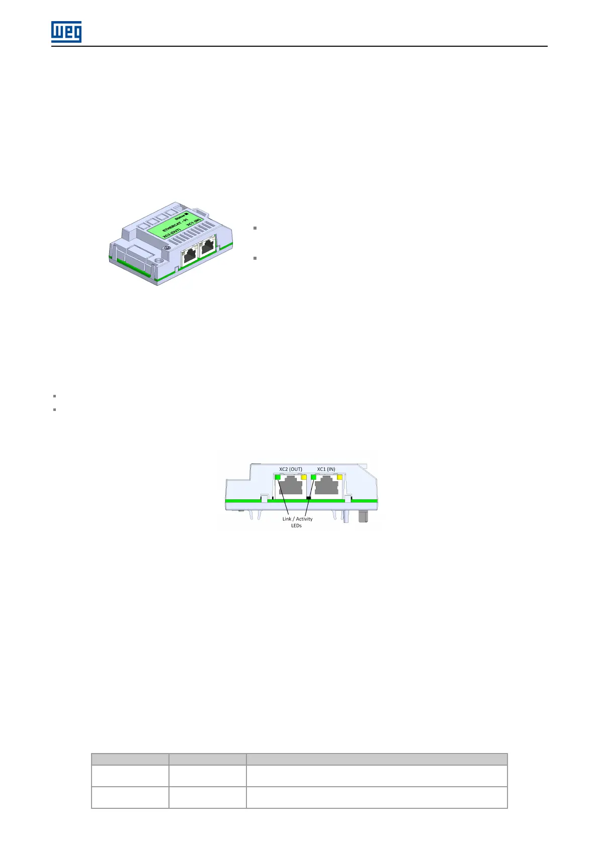
Two RJ45 connectors are available for network connection:
XC1 (IN): used to connect to the segment that comes from master side.
XC2 (OUT): used to connect to the segment that leads to the other slaves (or not connected, if it is the last device
on the network).
Figure 3.1: Connectors and LEDs of EtherCAT accessory
The connectors pinout follows the Fast Ethernet 100BASE-TX standard, using two pairs of cables (standard
connection, straight-through) for transmitting and receiving data.
EtherCAT accessory makes the protective earth connection through the fixing screw. The connectors frame, which
are usually connected to the cable shield, are short circuited, and a RC circuit connects them to the protective earth.
3.3 INDICATION LEDS
EtherCAT accessory has a LED indicator on each Ethernet port, and a bicolor LED for diagnostics (Status). These
LEDs have the following functions and indications:
Table 3.1: EtherCAT indication LEDs
LED Color Function
Link/Activity
(IN/OUT)
Green Indication of link and activity, one for each Ethernet port.
Status Bicolor
(Green/Red)
Module state; indicate the state of EtherCAT slave.
CFW11 | 8