www.weg.net
Automatic Voltage Regulator – GRT7-TH4E / GRT7-TH4PE l 13
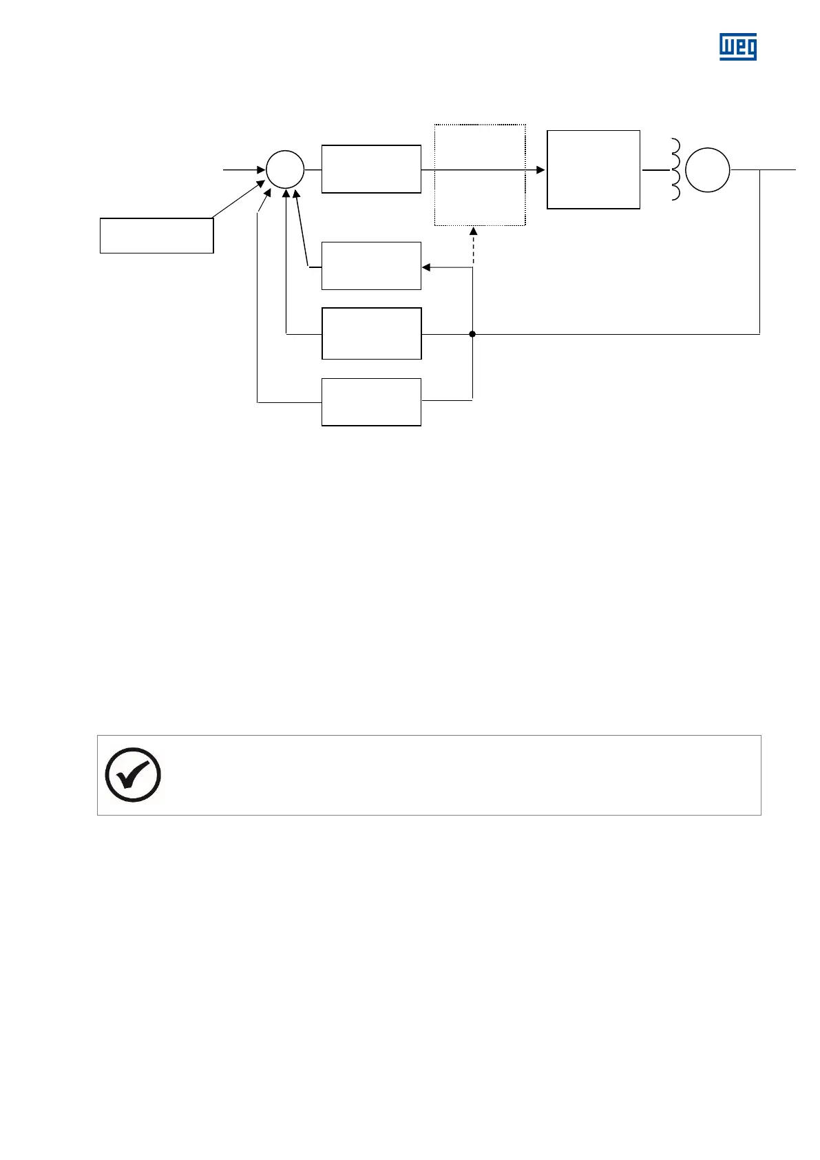
6 BLOCK DIAGRAM
Figure 6.1: Block diagram
7 TRIMPOTS FUNCTION
P1: Voltage adjustment
P2: Droop adjustment
P3: Stability 2 adjustment
P4: Stability 1 adjustment
P5: Under frequency adjustment
8 TRIMPOTS ADJUSTMENT
P1: Rotating CW, voltage increases.
P2: Rotating CW, reactive compensation range increases.
P3: Rotating CW, dynamic response will be slower.
P4: Rotating CW, dynamic response will be slower.
P5: Rotating CW, U/F range increases and rotating CCW, it decreases.
NOTE
* A potentiometer may be connected for fine voltage adjustment (5kΩ/3W) at terminals 6 and 7.
* The P3, P4 and P5 trimpots were set as default and sealed, but if adjustments are required, they can be
performed according to the procedures described in this manual.