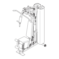
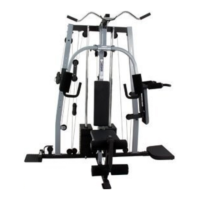
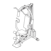
ASSEMBLY
• As you assemble the weight system,make sure
all parts are orientedas shown in the drawings.
Before beginning assembly, carefully rend the
following Information and Instructions:
• Assemblyrequirestwo people.
• Place all parts in a cleared area and remove the
packing materials. Do not disposeof the packing
materials untilassembly iscompleted.
• "13ghtenall partsas you assemble them, unless
instructedto do otherwise.
• For help identifyingsmall parts, use the PART
The following tools (not Included) are required
for assembly:
• two adjustable wrenches
• one rubber mallet
• one standard screwdriver
• one Phillips screwdriver
• lubricant, such as grease or petroleum jelly,
and soapy water.
Assemblywillbe moreconvenientifyou have a
socketset, a set of open-end or closed-end
wrenches, or a set of ratchetwrenches.
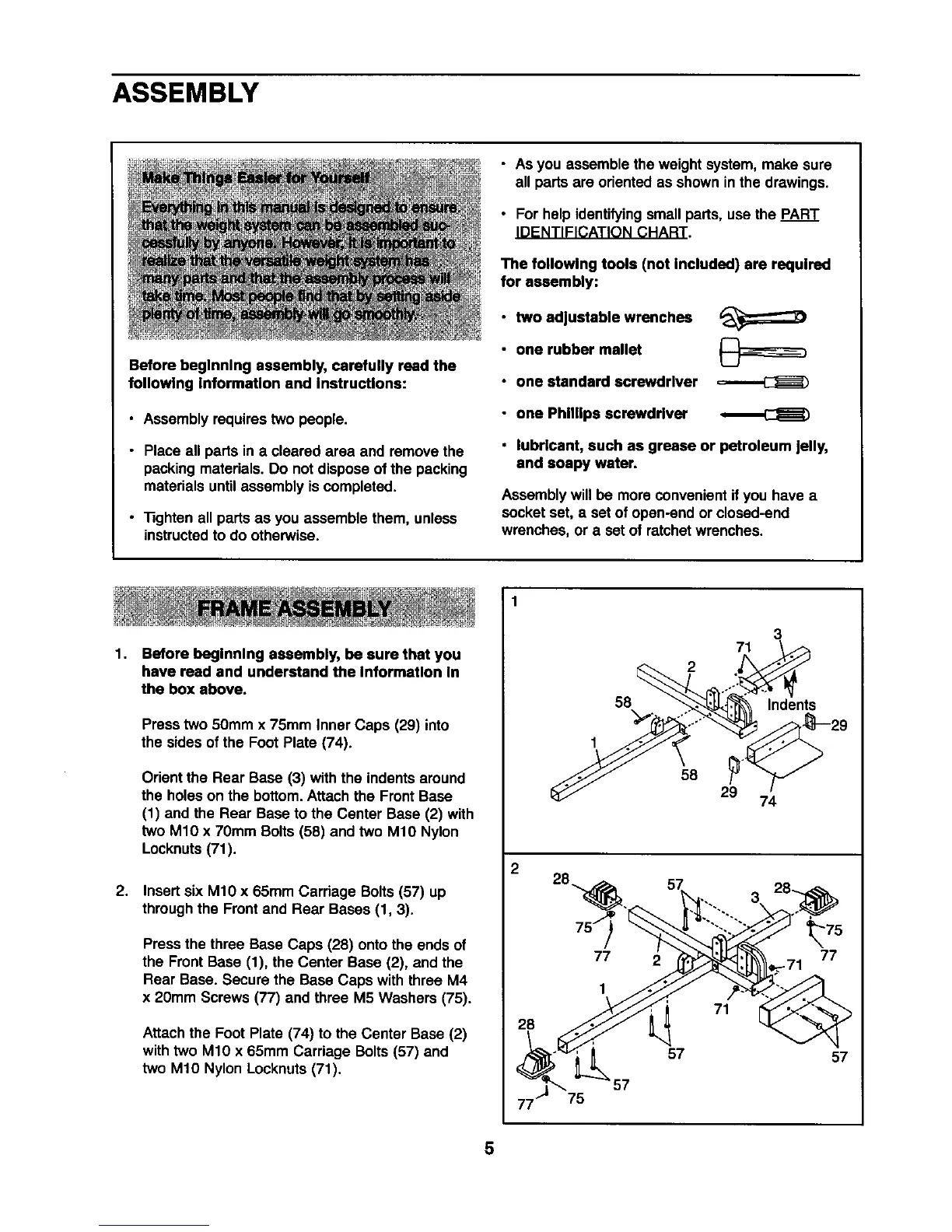
1.
2.
Before beginning assembly, be sure that you
have rend and understand the Information In
the box above.
Presstwo 50mm x 75mm Inner Caps (29) into
the sides ofthe Foot Plate (74).
Orientthe Rear Base (3) with the indents around
the holeson the bottom.Attach the Front Base
(1) and the Rear Base tothe Center Base (2) with
two M10 x 70mm Bolts (58) and two M10 Nylon
Locknuts(71).
Insertsix M10 x 65mm Carriage Bolts (57) up
throughthe Frontand Rear Bases (1, 3).
Press the three Base Caps (28) onto the ends of
the Front Base (1), the Center Base (2), and the
Rear Base. Secure the Base Caps withthree M4
x 20mm Screws (77) and three M5 Washers (75).
Attachthe Foot Plate (74) to the Center Base (2)
withtwo M10 x 65mm Carriage Bolts (57) and
two M10 Nylon Locknuts(71).
2
28
75
3
71
2
58 Indents
1
58
29
74
77
1
2
71
_75
77
-71
57 57
5